Mazda MX-5 (2000) – fuse box diagram
Year of production: 2000
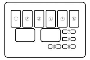
Fuse block (Engine compartment)

engine compartment
| Position | Description | Fuse rating [A] | Protected component |
| 1 | HEAD | 40 | Headlights |
| 2 | FUEL INJ | 30 | Fuel injection, Alternator |
| 3 | MAIN | 100 | For protection of all circuits |
| 4 | IG KEY | 60 | All ignition related circuits |
| 5 | BLOWER | 30 | Blower motor |
| 6 | FAN | 30 | Cooling fan, Additional fan (air conditioner)* |
| 7 | BTN 1 | 30 | Taillights*, Turn signal lights, Instrument panel illumination8, Auto antenna* |
| 8 | BTN 2 | 20 | Rear defroster*, Audio amp* |
| 9 | ABS | 20 | Antilock brake system* |
| 10 | STOP | 15 | Brake lights, Horn, Shift lock |
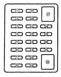
Fuse panel (Driver’s side)

| Position | Description | Fuse rating [A] | Protected component |
| 1 | ROOM | 10 | Interior light, Auto antenna, Warning buzzers |
| 2 | DEFOG | 15 | Rear defroster* |
| 3 | TAIL | 15 | Tail lights, Front parking lioghts, Slide marker lights |
| 4 | HAZARD | 10 | Turn signal lights |
| 5 | D.LOCK* | 10 | Power door lock* |
| 6 | AUDIO* | 20 | Audio amp* |
| 7 | CIGAR | 20 | Cigar lighter |
| 8 | RADIO | 10 | Audio |
| 9 | WIPER | 20 | Windshield wipers ans washer |
| 10 | A/C | 10 | Air conditioner* |
| 11 | P.WIND | 30 | Power windows |
| 12 | F.FOG* | 20 | Fog lights |
| 13 | ENGINE | 15 | Engine control system |
| 14 | METER | 15 | Instrument cluster |
| 15 | TURN | 10 | Turn signal lights |
| 16 | A/B | 10 | Suplemental restraint system, Antilovk brake system |
| 17 | — | — | — |
| 18 | ST.SIG* | 10 | Instrument cluster, Cruise control* |
| 19 | R.FOG* | 10 | — |
| 20 | HEAD.RH | 15 | Headlights (RH) |
| 21 | HEAD.LH | 15 | Headlights (LH) |
| 22 | — | — | — |
| * – some models | |||
WARNING: Terminal and harness assignments for individual connectors will vary depending on vehicle equipment level, model, and market.
