Saab 9-3 (2006) – fuse box diagram
Year of production: 2006
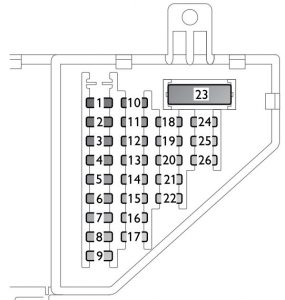
Instrument panel
 Saab 9-3 – fuse box – instrument panel
| No. |
Ampere rating [A] |
Function |
| 1 |
15 |
Steering wheel lock |
| 2 |
5 |
Steering column unit; ignition switch |
| 3 |
10 |
Hands-free 3; CD-player 3/CD-changer in cabin 3; SID |
| 4 |
10 |
Main instrument unit; manual climate control; automatic climate control (ACC) 3 |
| 5 |
7,5 |
Control module in front doors; Park Brake Shift Lock (automatic transmission) |
| 6 |
7,5 |
Brake light switch |
| 7 |
20 |
Dash fuse panel; fuel filler door |
| 8 |
30 |
Control module in passenger front door |
| 9 |
10 |
Dash fuse panel |
| 10 |
30 |
Trailer socket 3; electrical socket in storage compartment between seats 3 |
| 11 |
15 |
Data link connection (diagnostics) |
| 12 |
15 |
Interior lighting incl. glove box |
| 13 |
20 |
Accessories |
| 14 |
20 |
Radio, sound system I 3; control panel, Infotainment System 3 |
| 15 |
30 |
Control module in driver’s door |
| 16 |
5 |
Passenger Sensing System |
| 17 |
— |
— |
| 18 |
7,5 |
Manual climate control 3 |
| 19 |
— |
— |
| 20 |
7,5 |
Headlight levelling switch |
| 21 |
7,5 |
Hands-free 3; brake light switch; manual climate control 3; clutch pedal switch |
| 22 |
30 |
Cigarette lighter 3 |
| 23 |
40 |
Cabin fan |
| 24 |
7,5 |
Airbag control module |
| 25 |
— |
— |
| 26 |
5 |
Yaw sensor (cars with ESP) |
| 27 |
— |
— |
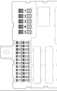
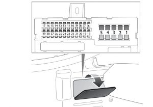
Trunk fuse panel, left-hand side
 Saab 9-3 – fuse box – trunk panel (Sport Sedan)
 Saab 9-3 – fuse box – trunk panel (convertible)
| No |
Ampere ratig [A] |
Function |
| 1 – 5 |
MAXI |
— |
| 6 |
30 |
Control module in left rear door |
| 7 |
30 |
Control module in right rear door |
| 8 |
20 |
Trailer 3 |
| 9 |
— |
— |
| 10 |
30 |
Left-hand brake light; rear right turn signal; right tail light; right reversing light; high-mounted brake light; trailer lights |
| 11 |
— |
— |
| 12 |
— |
— |
| 13 |
— |
— |
| 14 |
— |
— |
| 15 |
15 |
Seat heating, left seat |
| 16 |
15 |
Seat heating, right seat |
| 17 |
7,5 |
Autodimming rearview mirror; rain sensor; tire pressure monitoring |
| 18 |
15 |
Sunroof |
| 19 |
7,5 |
Telematics (OnStar) |
| 20 |
7,5 |
DVD player (navigation system) |
| 21 |
7,5 |
Saab Parking Assistance (SPA); control module in rear doors |
| 22 |
30 |
Amplifier, sound system III |
| 23 |
— |
— |
| 24 |
10 |
Movement sensor; CD changer in trunk (accessory) |
| 25 |
30 |
Electrically adjustable driver’s seat with memory |
| 26 |
30 |
Right-hand stop light; rear left turn signal; left tail light; rear fog light; left reversing light; license plate lighting; trunk lighting; trailer lights |
| 27 |
10 |
Convertible: Lumbar support, electrically adjustable front seat |
| 28 |
15 |
Telematics |
| 29 |
— |
— |
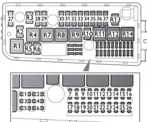
Fuse panel in engine bay
 Saab 9-3 – fuse box – engine compartment
| Number |
Ampere rating [A] |
Function |
| 1 |
— |
— |
| 2 |
10 |
Engine control module; automatic transmission control module |
| 3 |
20 |
Horn |
| 4 |
10 |
Engine control module; battery disconnect switch |
| 5 |
— |
— |
| 6 |
10 |
Selector lever, automatic transmission |
| 7 |
— |
— |
| 8 |
5 |
Relay for vacuumpump (brake system) 3 |
| 9 |
— |
— |
| 10 |
— |
— |
| 11 |
— |
— |
| 12 |
10 |
Washer fluid pump, rear window 3 |
| 13 |
— |
— |
| 14 |
— |
— |
| 15 |
30 |
Washer fluid pump, headlights |
| 16 |
30 |
Front right parking light; front right turn signal; left and right side turn signal; right high beam; left low beam; front left fog light |
| 17 |
30 |
Windshield wiper motor, low speed |
| 18 |
30 |
Windshield wiper motor, high speed |
| 19 |
20 |
Parking heater; auxiliary heater |
| 20 |
10 |
Headlight levelling |
| 21 |
— |
— |
| 22 |
30 |
Washer fluid pump, windshield |
| 23 |
— |
— |
| 24 |
20 |
Flash-to-pass |
| 25 |
20 |
Amplifier, sound system II |
| 26 |
30 |
Front left turn signal; front left parking light; front right fog light; right low beam; left high beam |
| 27-37 |
MAXI |
— |
| No. |
Function |
| R1 |
Washer fluid pump, windshield |
| R2 |
— |
| R3 |
— |
| R4 |
— |
| R5 |
Extra lights |
| R6 |
Horn |
| R7 |
— |
| R8 |
Starter motor |
| R9 |
Windshield wipers ON/OFF |
| R10 |
Washer fluid pump, rear window 3 |
| R11 |
Ignition +15 |
| R12 |
Windshield wipers, high/low speed |
| R13 |
— |
| R14 |
Washer fluid pump, headlights |
| R15 |
— |
| R16 |
— |
Fuse panel in front of battery
 Saab 9-3 – fuse box – fuse panel in front of battery
Fuse
| No. |
Ampere rating [A] |
Function |
| 1 |
— |
Air pump, secondary air 3 |
| 2 |
20 |
Fuel pump; preheated oxygen sensors (lambda probe) |
| 3 |
10 |
A/C compressor |
| 4 |
30 |
Main relay |
Relay
| No. |
Function |
| 1 |
— |
| 2 |
A/C-compressor |
| 3 |
Preheated oxygen sensors (lambda probe) |
| 4 |
Main relay, engine (ECM/EVAP/injectors) |
WARNING: Terminal and harness assignments for individual connectors will vary depending on vehicle equipment level, model, and market.


