Skoda Citigo (2012) – fuse box diagram
Year of production: 2012
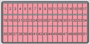
Fuse box under of the dash panel
The fuses are located underneath the steering wheel on the underside of the dash panel.

underside of dash panel
| Number | Power consumer |
| 1 | Telephone, radiator fan, instrument cluster, engine control unit |
| 2 | Diagnostic connection, relay for AC compressor |
| 3 | Clutch pedal switch, brake pedal switch |
| 4 | Daylight driving lights |
| 5 | Switch wiring harness |
| 6 | Headlamp beam adjustment, exterior mirror adjust |
| 7 | Not assigned |
| 8 | Not assigned |
| 9 | Park Assist |
| 11 | Low beam |
| 12 | Rear fog light |
| 13 | Low beam |
| 14 | Rear window wiper |
| 15 | Light switch |
| 16 | Steering force assistance |
| 17 | Windscreen washer |
| 18 | Reverse light switch |
| 19 | Injection valve, water pump |
| 20 | ABS/ESP, switch wiring harness |
| 21 | Switch illumination, number plate light |
| 22 | Daylight driving lights |
| 23 | Light switch |
| 24 | Switch wiring harness |
| 25 | Switch wiring harness |
| 26 | Switch wiring harness |
| 27 | Interior light |
| 28 | Diagnostic connector |
| 29 | Vehicle voltage control unit |
| 30 | Exterior mirror heater |
| 31 | Coller fan, regulator valve, lambda probe |
| 32 | Turn signal, brake light |
| 33 | Main beam |
| 34 | Instrument cluster, main beam |
| 35 | Not assigned |
| 36 | Cigarette lighter, 12-volt power socket |
| 37 | Air blower for heating and air conditioning |
| 38 | Radio |
| 39 | Panoramic sliding roof, horn |
| 40 | Engine control unit |
| 41 | Central locking system |
| 42 | Ignition module |
| 43 | Seat heaters |
| 44 | Fuel pump relay |
| 45 | Light switch |
| 46 | Rear window heater |
| 47 | Power windows – right |
| 48 | Horn |
| 49 | Front window wiper |
| 50 | Fog lights |
| 51 | Power windows – left |
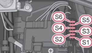
Fuse box in engine compartment
The fuses are located underneath a cover next to the vehicle battery.

| Number | Power consumer |
| 51 | ABS/ESP |
| 52 | Radiator fan |
| 53 | Battery management, control unit for radiator fan |
| 54 | ABS/ESP |
| 55 | Vehicle voltage control unit |
| 56 | Ignition lock, relay for starter |
Fuse box in the dash panel
These fuses are located in vehicles with the START-STOP system.

dash panel
| Number | Power consumer |
| 1 | ABS/ESP |
| 2 | Instrument cluster |
| 3 | Radio, diagnosis |
| 4 | DC-DC voltage converter, coils of the starter relay |
| 5 | Not assigned |
| 6 | Relay for fresh air/heat blower |
| 7 | Control unit for the AC system |
| 8 | Not assigned |
| 9 | Right light |
| 10 | Left light |
| 11 | Starter |
| 12 | DC-DC voltage converter |
WARNING: Terminal and harness assignments for individual connectors will vary depending on vehicle equipment level, model, and market.
