Hyundai Sonata (2005 – 2008) – fuse box diagram
Year of production: 2005, 2006, 2007, 2008
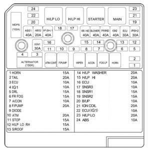
Engine Compartment

| Description | Ampere rating [A] | Protected component | ||
| FUSIBLE LINK | ABS.1 | 40 | ABS/ESC control module, Multipurpose check connector | |
| ABS.2 | 20 | ABS/ESC control module, Multipurpose check connector | ||
| I/P B+1 | 40 | Fuse 23, 24, 30, 31, 32, 33, 34, 35 | ||
| RR HTD | 40 | Defogger relay | ||
| BLOWER | 40 | Blower relay | ||
| P/WDW | 40 | Power window relay, Fuse 16 | ||
| IGN.2 | 40 | Start relay, Ignition switch (IG2, START) | ||
| ECU RLY | 30 | Engine control unit relay | ||
| I/P B+2 | 30 | Power connector 1/2, Fuse 21,22 | ||
| IGN.1 | 30 | Ignition switch (ACC, IG1) | ||
| ALT | 150 | Fusible Iink (ABS. 1, ABS. 2, RR HTD, BLOWER) | ||
| MDPS | 100 | (Spare) | ||
| FUSE | 1 | HORN | 15 | Horn relay |
| 2 | TAIL | 20 | Tail light relay | |
| 3 | ECU | 10 | PCM | |
| 4 | IG1 | 10 | (Spare) | |
| 5 | DRL | 15 | Siren relay, DRL control module | |
| 6 | FR FOG | 15 | Front fog light relay | |
| 7 | A/CON | 10 | A/C relay | |
| 8 | F/PUMP | 20 | Fuel pump relay | |
| 9 | DIODE | — | (Spare) | |
| 10 | ATM | 20 | ATM control relay | |
| 11 | STOP | 15 | Stop light relay | |
| 12 | H/LP LO RH | 15 | (Spare) | |
| 13 | S/ROOF | 15 | Sunroof control module | |
| 14 | H/LP WASHER | 20 | Headlight washer motor | |
| 15 | H/LP HI | 20 | Headlight relay (High) | |
| 16 | ECU | 10 | (Spare) | |
| 17 | SNSR.3 | 10 | Oxygen sensor, Fuel pump relay | |
| 18 | SNSR.1 | 15 | Mass air flow sensor, Crankshaft/Camshaft position sensor, Oil control valve, SMATRA | |
| 19 | SNSR.2 | 15 | A/C relay, Cooling fan relay, Injectors | |
| 20 | B/UP | 10 | Back up light switch, Pulse generator, Vehicle speed sensor | |
| 21 | IGN COIL | 20 | Ignition coils, Condenser | |
| 22 | ECU (IG1) | 10 | PCM | |
| 23 | H/LP LO | 20 | Headlight relay (Low) | |
| 24 | ABS | 10 | ABS/ESC control module, Multipurpose check connector | |
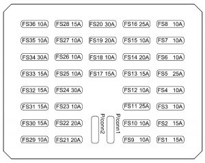
Inner Panel

| Fuse | Ampere rating [A] | Protected component |
| 1 | 15 | (Spare) |
| 2 | 15 | Seat warmer switch |
| 3 | 10 | BCM (Body Control Module), Sunroof control module, Electronic chrome mirror |
| 4 | 10 | ESC module, High blower relay, Humidity sensor |
| 5 | 25 | Cigarette lighter |
| 6 | 10 | (Spare) |
| 7 | 10 | Illumination lights, Right : License light, Rear combination light, Headlight, Glove box light |
| 8 | 10 | Front fog light relay, Left : License light, Rear combination light, Headlight |
| 9 | 10 | Headlight washer relay, Right headlight leveling actuator |
| 10 | 10 | DRL control module, Headlight relay, AQS and ambient sensor, Left headlight leveling actuator |
| 11 | 25 | Wiper and washer |
| 12 | 10 | A/C control module |
| 13 | 15 | SRS control module, Passenger’s Airbag switch |
| 14 | 10 | Front accessory socket, Rear power outlet |
| 15 | 10 | Digital clock, Audio, A/T shift lock control module, Power outside mirror and mirror folding |
| 16 | 25 | Safety window module |
| 17 | 15 | (Spare) |
| 18 | 10 | A/T shift lock control module |
| 19 | 20 | Power window main switch, Left rear power window switch |
| 20 | 30 | Power window main switch, Right power window switch |
| 21 | 20 | Audio amp |
| 22 | 20 | Door lock/unlock relay |
| 23 | 10 | Hazard switch, Hazard relay |
| 24 | 30 | Power seat manual switch(RHD) |
| 25 | 10 | Instrument cluster |
| 26 | 10 | Hazard switch |
| 27 | 10 | BCM(Body Control Module), Instrument cluster, Yaw rate sensor, ESC switch |
| 28 | 15 | (Spare) |
| 29 | 10 | Burglar alarm relay |
| 30 | 15 | (Spare) |
| 31 | 15 | Rear fog light relay |
| 32 | 15 | Trunk lid relay, Fuel filler door and trunk lid switch |
| 33 | 15 | (Spare) |
| 34 | 30 | Power seat manual switch |
| 35 | 10 | Sport mode switch, Key solenoid |
| 36 | 10 | A/C control module, Outside mirror and mirror folding motor |
| CONNECTOR. 1 | 15 | Audio |
| CONNECTOR. 2 | 15 | BCM(Body Control Module), Digital clock, Instrument cluster, A/C control module, Courtesy lights |
WARNING: Terminal and harness assignments for individual connectors will vary depending on vehicle equipment level, model, and market.
