KIA Cadenza (IG) (2017 – 2018) – fuse box diagram
Year of production: 2017, 2018
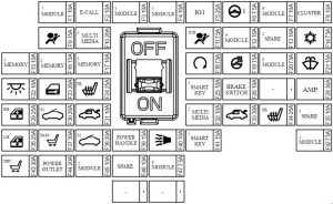
Instrument panel fuse panel

| No. | A | Circuit Protected |
| F1 | 10 | Driver Door Module, Passenger Door Module |
| F2 | 10 | MTS E-Call Module |
| F3 | 10 | Stop Lamp Switch, BCM, Sports Mode Switch |
| F4 | 10 | Console Switch, Blind Spot Detection Radar LH/RH, BCM, Smart Cruise Control Unit Crash Pad Switch, Fuel Filler & Trunk Open Switch, Lane Departure Warning Unit |
| F5 | 25 | E/R Junction Block (Fuse F36, F41, F42) |
| F6 | 7.5 | MDPS Unit |
| F7 | 10 | A/C Switch, A/C Control Module, Electro Chromic Mirror, Head Lamp LH/RH, Auto Head Lamp Leveling Device Module,Front Seat Warmer Control Module, Front Air Ventilation Seat Control Module, Rear Seat Warmer Control Module, A/V & Navigation Head Unit, MTS E-Call Module, Driver IMS Module, ATM Shift Lever Indicator, Multipurpose Check Connector |
| F8 | 10 | Instrument Cluster, Head-Up Display |
| F9 | 15 | SRS Control Module |
| F10 | 20 | IGPM (Fuse F32), Audio, A/V & Navigation Head Unit |
| F11 | 7.5 | A/C Switch, Instrument Cluster |
| F12 | 10 | Smart Key Control Module, Immobilizer Module |
| F13 | 10 | Spare |
| F14 | 7.5 | A/C Switch, A/C Control Module, Ionizer, E/R Junction Block(RLY.I) |
| F15 | 10 | Head-Up Display, Instrument Cluster, Wireless Charger Unit, Analog Clock, BCM, Rain Sensor, Driver Door Module, Power Trunk Module, Passenger Door Module, A/C Switch, A/C Control Module, Security Indicator |
| F16 | 15 | Driver Door Module |
| F17 | 10 | Passenger Door Module |
| F18 | 7.5 | Transaxle Range Switch, ECM/PCM |
| F19 | 15 | BCM |
| F20 | 7.5 | Surround View Unit, Rear Seat Warmer Control Module, Front Seat Warmer Control Module, Front Air Ventilation Seat Control Module |
| F21 | 15 | Multifunction Switch |
| F22 | 10 | Glove Box Lamp, Passenger Foot Lamp, Driver Foot Lamp, Trunk Room Lamp, Front Vanity Lamp Switch LH/RH, Overhead Console Lamp, Room Lamp, Rear Personal Lamp LH/RH |
| F23 | 20 | Door Lock/Unlock Relay |
| F24 | 25 | Front Seat Warmer Control Module, Front Air Ventilation Seat Control Module |
| F25 | 10 | Start/Stop Button Switch |
| F26 | 10 | Stop Lamp Switch, Immobilizer Module, Smart Key Control Module |
| F27 | – | – |
| F28 | 30 | AMP |
| F29 | 25 | Passenger Safety Power Window Module, Rear Power Window Switch RH |
| F30 | 20 | Sunroof Control Unit (Glass) |
| F31 | 10 | Trunk Relay, Fuel Filler & Trunk Open Switch, E/R Junction Block(RLY.H) |
| F32 | 10 | Front Monitor |
| F33 | 30 | Power Trunk Module |
| F34 | 25 | Rear Seat Warmer Control Module |
| F35 | 10 | Spare |
| F36 | 25 | Rear Power Window Switch LH, Driver Safety Power Window Module |
| F37 | 30 | Passenger Seat Manual Switch |
| F38 | 20 | Sunroof Control Unit (Roller) |
| F39 | 15 | Not Used |
| F40 | 10 | Burglar Alarm Horn Relay |
| F41 | 15 | Smart Key Control Module |
| F42 | 7.5 | Data Link Connector, Hazard Switch, Console Switch |
| F43 | 30 | Driver Seat Manual Switch, Driver IMS Module |
| F44 | 20 | Front Power Outlet |
| F45 | 10 | Rear Seat Console Switch, AMP, Surround View Unit, BCM, MTS E-Call Module, A/C Control Module, Analog Clock, Wireless Charger Unit, A/C Switch, Smart Key Control Module, Audio, Front Monitor, AA/ & Navigation Head Unit, E/R Junction Block(RLY.5) |
| F46 | 10 | Spare |
| F47 | 7.5 | BCM, Smart Key Control Module |
Engine compartment fuse box
| No. | A | Circuit Protected |
| F1 | 80 | MDPS UNIT |
| F2 | 60 | IGPM (Fuse F28, IPS1, IPS3, IPS5, IPS8) |
| F4 | 50 | E/R Junction Block (RLY.1) |
| F5 | 50 | IGPM (Fuse F42, IPS2, IPS4, IPS6, IPS7) |
| F6 | 50 | E/R Junction Block (RLY.12) |
| F7 | 40 | ESP Control Module |
| F9 | 40 | Not Used |
| F10 | 30 | W/O Smart Key: E/R Junction Block (RLY.6), Ignition Switch With Smart Key: E/R Junction Block (RLY.6), PCB Block, (IG2 Relay) |
| F12 | 80 | PCB BLOCK (Fuse F39,F38, F47, F52, Engine Relay) |
| F13 | 60 | IGPM (Fuse F29, F30, F31, F33, F34, F36, F37, F38, F40, F43) |
| F14 | 60 | E/R Junction Block (RLY.2, RLY.3) |
| F16 | 50 | IGPM (Fuse F23, F24, F25, F26, F41, Leak Current Autocut Relay) |
| F17 | 40 | E/R JUNCTION BLOCK (RLY.5) |
| F19 | 40 | W/O Smart Key: Ignition Switch With Smart Key: PCB Block, (IG1, ACC Relay) |
| F20 | 30 | ESP Control Module, Multipurpose Check Connector |
| F22 | 30 | E/R Junction Block (RLY.8) |
| F23 | 40 | Not Used |
| F24 | 15 | TCM |
| F25 | 10 | Smart Cruise Control Unit |
| F26 | 10 | Battery Sensor |
| F27 | 20 | E/R Junction Block (RLY.9) |
| F28 | 10 | E/R Junction Block (RLY.7) |
| F29 | 20 | Not Used |
| F30 | 20 | Not Used |
| F31 | 10 | A/C Control Module |
| F32 | 10 | BCM |
| F33 | 10 | A/C Switch, Driver/Passenger Power Outside Mirror |
| Relay | ||
| RLY.01 | Blower Relay | |
| RLY.02 | Cooling Fan1 Relay | |
| RLY.03 | Cooling Fan2 Relay | |
| RLY.04 | E-Cvvt Relay | |
| RLY.05 | Power Outlet Relay | |
| RLY.06 | Start Relay | |
| RLY.07 | B.UP Relay | |
| RLY.08 | H/LAMP Washer Relay | |
| RLY.09 | Front Deicer Relay | |
| RLY.11 | Fuel Filler Relay | |
| RLY.12 | Rear Heated Relay | |
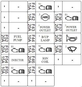
PCB Block (engine compartment fuse box)

| No. | A | Circuit Protected |
| F36 | 10 | ECM |
| F37 | 20 | Front Power Outlet & Cigarette Lighter |
| F38 | 20 | PCB Block (Horn Relay) |
| F39 | 30 | PCB Block (Wiper Power Relay) |
| F41 | 15 | TCM, Transaxle Range Switch |
| F42 | 10 | ESP Control Module |
| F43 | 20 | Rear Power Outlet |
| F44 | 10 | Electro Chromic Mirror, Front Monitor, Audio, Rear Combination Lamp (IN) LH/RH, MTS E-Call Module |
| F45 | 15 | Oxygen Sensor #1~#4 |
| F46 | 20 | Ignition Coil #1~#6 |
| F47 | 10 | ECM |
| F52 | 20 | PCB Block (Fuel Pump Relay) |
| F53 | 20 | ECM |
| F54 | 15 | Not Used |
| F55 | 10 | Variable Intake Solenoid Valve #1, #2, Electronic Thermostat, Purge Control Solenoid Valve, Oil Pressure Solenoid Valve, Oil Control Valve #1~#4, E/R Junction Block (RLY.2, RLY.3), PCB Block (Fuel Pump Relay) |
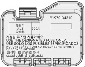
Main fuse

WARNING: Terminal and harness assignments for individual connectors will vary depending on vehicle equipment level, model, and market.
