Iran Khodro Runna – fuse box diagram
Year of production:
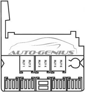
Fuse box on engine compartment


| № |
A |
Protected Component |
| 1 | 40 | Power supply for ignition switch – Immobilizer |
| 2 | 20 | SPS*: Power supply of front node internal systems |
| 30 | Relay switch for fog lamp – horn | |
| 3 | 20 | SPS*: Connector power supply of front node internal systems |
| 40 | Connector power supply of BCM internal systems | |
| 4 | 20 | SPS*: Connector power supply of front node internal systems |
| 30 | Connector power supply of BCM internal systems | |
| 5 | 10 | SPS*: Relay switch for small lights |
| 6 | — | Spare |
| 7 | 40 | SPS*: Brake (ABS) |
| 30 | Brake (ABS) | |
| 8 | 30 | Brake (ABS) |
| 9 | 40 | SPS*: Fan (High and Low speed) Connector power supply of BCM internal system |
| 10 | 70 | SPS*: Connector power supply of BCM internal systems |
| 50 | Connector power supply of BCM internal systems | |
| 11 | 20 | SPS*: Relay switch for horn |
| 40 | Connector power supply of BCM internal systems | |
| 12 | 30 | SPS*: Starter supply |
| 20 | Front node supply | |
| 13 | 15 | Front node supply |
| 14 | 30 | Relay switch for front windshield wiper |
| 15 | 10 | SPS*: Sensor oxygen power |
| 16 | 40 | SPS*: Double relay supply |
| 30 | Double relay supply | |
| 17 | 10 | Fuel pump supply and Engine unit |
| 18 | 10 | Engine unit supply |
| Relay | ||
| R1 | — | Relay switch for engine control |
| R2 | — | Relay switch for fuel pump |
| R3 | — | Relay switch for small light Relay switch for fog lamp |
| R4 | — | Relay switch for horn |
| R5 | — | Relay switch for front windshield wiper |
| R6 | — | Relay switch for front windshield wiper |
| *Sazeh Pooyesh System | ||
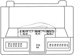
Fuse Box Under Dashboard (T1)

| № |
A |
Protected Component |
| F1 | — | Reserve |
| F2 | 5 | Heating fan relay |
| F3 | 5 | Power supply of front node FCM, cooler, Instrument panel |
| F4 | 10 | Power supply of rear wiper motor and trunk lock |
| F5 | 5 | Power supply of background light |
| F6 | 5 | Power supply of anti-lock braking system ABS |
| F7 | 10 | Power supply of airbag unit |
| F8 | 5 | Power supply of Instrument panel, immobilizer, DIAG, ECU |
| F9 | 5 | Power supply of wiper washer pumps |
| F10 | 5 | Power supply of central node of BCM, Front windows requlator display, reverse pear sensor. |
| F11 | 10 | Power supply of reverse gear |
| F12 | 5 | Power supply of Brake Light Switch |
| F13 | 10 | A three-position switch power supply of Cooler |
| F14 | 5 | Power supply of ceiling lights, trunk |
| F15 | 20 | Power supply of Lighter |
| F16 | 10 | Power supply of Radio Player |
| F17 | — | Reserve |
| F18 | — | Reserve |
| F19 | — | Reserve |
| F20 | — | Reserve |
| F21 | — | Reserve |
| F22 | 10 | Power supply of Front Window Regulators |
| F23 | 5 | Power supply of mirrors heater |
| F24 | 30 | Power supply of rear glass heater |
| F25 | 30 | Power supply of central lock |
| F26 | 20 | Power supply of central node BCM |
| F27 | 5 | Power supply of relays, monitors Cooler |
| F28 | 20 | Power supply of central node BCM |
| F29 | 5 | Power supply of Immobilizer |
| F30 | 10 | Power supply of radio memory |
| F31 | — | Reserve |
| F32 | — | Reserve |
| F33 | 40 | Power supply of Heater Fan |
| F34 | 40 | Power supply of front windows regulator, mirror |
| F35 | 40 | Power supply of rear window Regulators |
| F36 | 5 | Reserve |
| F37 | 10 | Reserve |
| Relay | ||
| R1 | — | Fan Relay |
| R2 | — | Instrument panel relay, cooler and front node FCM |
| R3 | — | Voltage relay ECO |
| R4 | — | Rear of rear glass heater and side mirrors |
| R5 | — | Front wiper washer pump relay |
| R6 | — | |
| R7 | — | — |
| R8 | — | Rear window regulator Relay |
| R9 | — | Trunk opener and rear wiper relay |
| R10 | — | Central opener relay |
| R11 | — | Central door locking relay |
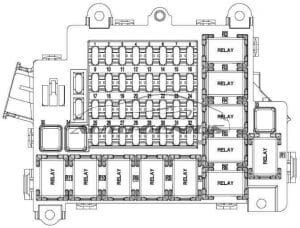
Fuse Box Under Dashboard (T2)

| № |
A |
Protected Component |
| F21 | — | Spare |
| F22 | 10 | Main switch supply (position 2) air bag unit and central node |
| F23 | 20 | Main switch supply (position 1) lighter |
| F24 | 10 | Main switch supply – position 1 (motivation of heater relay * Radio, brake light, front node, central node and instrument panel) |
| F25 | 10 | Radio permanent supply |
| F26 | 20 | Central node supply |
| F27 | 20 | Central node supply |
| F28 | 30 | Central node supply and main supply and motivation of rear door motive relay |
| F29 | 30 | Rear window control supply |
| F30 | 30 | Central node supply (Front lifting window) |
| F31 | 30 | Rear window heater |
| F32 | 30 | Heater fan supply |
| F33 | 30 | Engine ignition |
| F34 | 10 | Main switch supply (position 2) immobilizer, diagnostic connector, instrument panel, cooler gas pressure sensor, engine unit |
| F35 | 5 | Main switch supply (position 2), Anti-brake system (ABS) |
| F36 | 10 | Immobilizer permanent supply, diagnostic connector, instrument panel, motivation of window heater * windscreen washer pump, Multipurpose Instrument Panel |
| Relay | ||
| R1 | — | Front windscreen washer Pump |
| R2 | — | Trunk lid unlocking |
| R3 | — | Mirrors and rear window heater |
| R4 | — | Heater Fan |
| R5 | — | Rear Window Control |
| R6 | — | |
| R7 | — | |
| R8 | — | |
WARNING: Terminal and harness assignments for individual connectors will vary depending on vehicle equipment level, model, and market.
