Pontiac Sunfire (1995 – 2005) – fuse box diagram
Year of production: 195, 1996, 1997, 1998, 1999, 2000, 2001, 2002, 2003, 2004, 2005
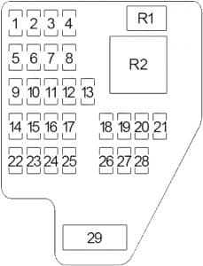
Passenger Compartment Fuse Box (’00-’05)
| No. | A | Circuit Protected |
| 1 | 20 | Ignition Module |
| 2 | 20 | ’02-’05: Accessory Power Outlet |
| 3 | 15 | Right Headlamp |
| 4 | 15 | Horn |
| 5 | 10 | Powertrain Control Module (PCM) |
| 6 | 10 | Anti-lock Brake Solenoids |
| 7 | 10 | Radio, Interior Lamps, OnStar |
| 8 | 10 | Daytime Running Lamps: Fog Lamps |
| 9 | 10 | Body Control Module, Instrument Panel Cluster |
| 10 | 10 | Cruise Control |
| 11 | 15 | Left Headlamp |
| 12 | 20 | Cigarette Lighter, Interior Lamps, Exterior Lamps |
| 13 | 20 | Stop Lamps, Hazard Lamps, Anti-lock Brakes, Cruise Control |
| 14 | 10 | Brake Transaxle Shift Interlock (BTSI), Cruise Control, HVAC Compressor Control, Multi-Port Injection |
| 15 | 15 | Air Bag |
| 16 | 10 | Power Mirror, Data Link Connector |
| 17 | 20 | Park Lamps, Side Marker Lamps, Instrument Panel Lamps |
| 18 | 15 | Power Door Locks, Convertible Top |
| 19 | 10 | Anti-lock Brake, Coolant Fan, HVAC: Compressor Control |
| 20 | 10 | Body Control Module |
| 21 | 10 | Cavalier: Amplifier |
| 20 | Sunfire: Amplifier | |
| 22 | 10 | Backup Lamps, Turn Signal Lamps |
| 23 | 15 | Fuel Pump, Fuel Injectors |
| 24 | 15 | ’01-’05: Remote Keyless Entry System |
| 10 | ’00: Remote Keyless Entry System | |
| 25 | 10 | Instrument Panel Cluster, Electronic Brake Control Module |
| 26 | 30 | Rear Window Defogger |
| 27 | 10 | O2 Sensor Heater |
| 28 | 25 | Wiper/Washer |
| Relay | ||
| 29 | 25 | Power Windows, Power Sunroof |
| 30 | Convertible: Power Windows, Convertible Top | |
| Relay | ||
| R1 | ’05: Headlamps | |
| R2 | Daytime Running Lamps | |
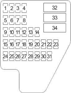
Passenger Compartment Fuse Box (’95-’99)

| No. | A | Protected Component |
| 1 | 20 | Engine Ignition, Multiport Fuel Injection |
| 2 | – | – |
| 3 | 10 | Headlamp |
| 15 | Right Headlamp | |
| 4 | – | – |
| 5 | 10 | Powertrain Control Module (PCM) |
| 6 | – | – |
| 7 | 10 | Alarm Module, Warning Chimes, Illuminated Entry, Trunk Lamp, Overhead Lamps, Map/Reading Lamps, Glove Box Lamp, Radio Power Mirrors |
| 8 | 10 | Daytime Running Lights, Fog Lamps |
| 9 | 10 | Alarm Module, Warning Chimes, Illuminated Entry |
| 10 | 10 | Cruise Control |
| 11 | 20 | Headlights (Flash to Pass) |
| 15 | Left Headlamp | |
| 12 | 15 | Cigarette Lighter, Horn, Diagnostic Connector, Asynchronous Receiver/Transmitter (UART) Link |
| 13 | 10 | Instrument Panel Lamps |
| 14 | 20 | Stop Lamps, Hazard Lamps, ABS, Cruise Control, Exterior Lights |
| 15 | 10 | Automatic Transaxle, Brake Transaxle Shift Interlock (BTSI), Cruise Control, HVAC: Compressor Control, EGR (2.2L), Canister Purge Valve, A/C High Pressure Switch (2.3L) |
| 16 | 15 | Air Bag-DERM (Diagnostic Energy Reserve Module) Power |
| 17 | – | – |
| 18 | 20 | Park Lamps, Side Marker Lamps, Instrument Panel Lamps |
| 19 | – | – |
| 20 | 20 | Power Door Locks, Convertible Top |
| 21 | 10 | Heater-A/C Control, Crankcase Vent Heater (2.3L), Rear Window Defogger, Antilock Brake System, Engine Cooling Fan (2.2L) |
| 22 | 10 | Radio/Audio Systems |
| 23 | – | – |
| 24 | 20 | Turn Signals, Back-Up Lights |
| 25 | 20 | Fuel Pump, Fuel Injectors |
| 26 | 10 | Air Bag-DERM (Diagnostic Energy Reserve Module) Crank Signal |
| 27 | 10 | Instrument Panel, Antilock Brake Control Module |
| 28 | 10 | Instrument Panel, Powertrain Control Module (PCM), Asynchronous Receiver/Transmitter (UART) Link |
| 29 | 30 | Rear Window Defogger |
| 30 | 10 | Rear Oxygen Sensor Heater (2.3L Cal. Auto) |
| 31 | 25 | Wiper/Washer |
| Relay | ||
| 32 | 20 | Headlight, Daytime Running Lights |
| 33 | – | – |
| 33 | 25 | Power Windows, Sunroof |
| 30 | Convertible: Power Windows, Convertible Top | |
Engine Compartment Fuse Box

| No. | A | Protected Component |
| 1 | 10 | ’95-’99: Starter and Charging System: Generator Voltage Sense |
| 2 | 10 | HVAC Compressor Control |
| 3 | 10 | PCM, Multiport Fuel Injection |
| 4 | 30 | HVAC Blower Control, HVAC Compressor Control |
| 5 | 15 | ’95-’99: ABS |
| 6 | 10 | ’02-’05: Starter Relay Control |
| 7 | – | – |
| 8 | 10 | ’95-’96: Tach |
| 9 | 50 | ’00-’05: Blower Relay Control, Multiport Fuel Injection |
| 10 | 30 | Cooling Fan |
| 11 | 50 | ’00-’05: ABS, Power Distribution |
| 40 | ’95-’99: ABS | |
| 12 | 40 | Power Distribution (Lighting) |
| 13 | 40 | Power Distribution (Power ACC/Stop Lamp) |
| 14 | 50 | Power Distribution, Starter, Ignition, Charging System |
| Relay | ||
| R1 | Blower Motor | |
| R2 | ’95-’99: ABS and Electronic Variable Orifice Steering | |
| R3 | Cooling Fan | |
| R4 | ’02-’05: Starter | |
| R5 | Fuel Pump | |
| R6 | Air Conditioner | |
WARNING: Terminal and harness assignments for individual connectors will vary depending on vehicle equipment level, model, and market.

