GMC Yukon (2021 – 2022) – fuse box diagram
Year of production: 2021, 2022
Engine Compartment Fuse Block
The engine compartment fuse block is in the engine compartment, on the driver side of the vehicle.
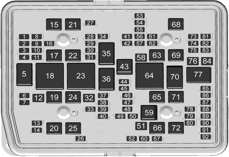
| № | Usage |
|---|---|
| 1 | – |
| 2 | – |
| 3 | – |
| 4 | – |
| 6 | Exterior Lighting Module 7 |
| 7 | Exterior Lighting Module 4 |
| 8 | – |
| 9 | Exterior Lighting Module 5 |
| 10 | Exterior Lighting Module 6 |
| 11 | Spare |
| 12 | – |
| 13 | Washer Front |
| 14 | Washer Rear |
| 15 | Rear Electrical Center 2 |
| 16 | Power Sounder |
| 17 | Spare |
| 19 | DC/AC Inverter |
| 20 | IECR 2 |
| 21 | – |
| 22 | IECL 2 |
| 24 | Electronic Brake Control Module |
| 25 | Rear Electrical Center 1 |
| 26 | Camera Wash |
| 27 | Horn |
| 28 | Headlamp Right |
| 29 | Headlamp Left |
| 30 | Exterior Lighting Module 3 |
| 31 | Exterior Lighting Module 1 |
| 32 | – |
| 33 | Not R/C |
| 34 | – |
| 37 | On Board Diagnostics (OBD) Body |
| 38 | MISC Body |
| 39 | Upfitter |
| 40 | MISC Instrument Panel (IP) |
| 41 | Trailer Parking Lamps |
| 42 | Right Taillamp |
| 44 | Trailer Tow |
| 45 | Secondary Axle Motor |
| 46 | Engine Control Module (ECM) Ignition |
| 47 | OBD Engine |
| 48 | – |
| 49 | Telematics Control Module |
| 50 | A/C Clutch |
| 51 | Transfer Case Control Module |
| 52 | Front Wiper |
| 53 | – |
| 54 | Left Taillamps |
| 55 | Trailer Back-up Lamp |
| 56 | Semi Active Damping System |
| 57 | Spare |
| 58 | Starter Motor |
| 60 | Active Fuel Management 1 |
| 61 | Automatic Lamp Control (ALC) Main |
| 62 | Integrated Chassis Control Module/ Canister Vent Solenoid/ Diesel Exhaust Fluid |
| 63 | Trailer Brake |
| 65 | Auxiliary Underhood Electrical Center |
| 66 | Left Cool Fan Motor |
| 67 | Active Fuel Management 2 |
| 68 | Automatic Lamp Control (ALC) Motor |
| 69 | Starter Pinion |
| 71 | Cool Fan Motor Lower |
| 72 | Right Cool Fan Motor/ Lower |
| 73 | Left Trailer Stop Turn Lamp |
| 74 | Trailer Interface Module 2 |
| 75 | Diesel Exhaust Fluid Controller |
| 76 | ELEC RNG BDS |
| 78 | Engine Control Module |
| 79 | – |
| 80 | Cabin Cool Pump 17W |
| 81 | Right Trailer Stop Turn Lamp |
| 82 | Trailer Interface Module 1 |
| 83 | Fuel Tank Zone Module |
| 84 | Trailer Battery |
| 85 | Engine |
| 86 | Engine Control Module |
| 87 | Injector B Even |
| 88 | O2 B Sensor |
| 89 | O2 A Sensor |
| 90 | Injector A Odd |
| 91 | Engine Control Module (ECM) Throttle Control |
| 92 | Cool Fan Clutch AERO Shutter |
| Relays | |
| 5 | – |
| 18 | DC/AC Inverter |
| 23 | – |
| 35 | Park Lamp |
| 36 | Run/Crank |
| 43 | Secondary Axle Motor |
| 59 | A/C Clutch |
| 64 | Starter Motor |
| 70 | Starter Pinion |
| 77 | Powertrain |
Passenger Compartment Fuse Box
The right instrument panel fuse block access door is on the passenger side edge of the instrument panel.
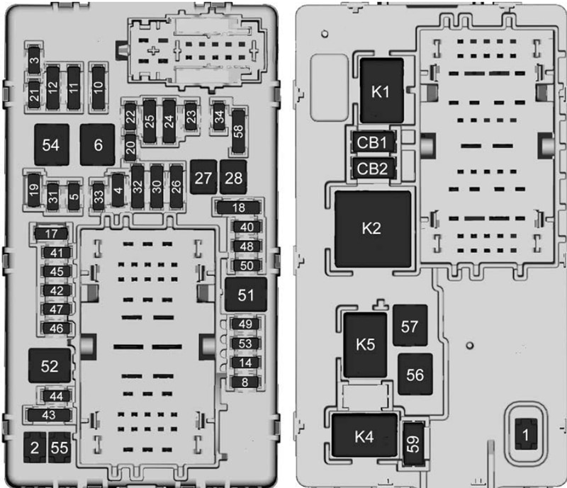
| № | Usage |
|---|---|
| F1 | Right Door |
| F2 | Left Door |
| F3 | Universal Garage Door Opener (UGDO)/ OnStar Hands-free Calling (OHC)/ Camera |
| F4 | Body Control Module 2 |
| F5 | Displays |
| F6 | Front Blower |
| F8 | Left Door Pane |
| F10 | Tilt/Column Lock |
| F11 | USB/ Data Link Connector (DLC) |
| F12 | Central Gateway Module (CGM)/ Onstar |
| F14 | Right Door Panel |
| F17 | Steering Wheel Control |
| F18 | Active Vibration Module 1 |
| F19 | – |
| F20 | – |
| F21 | – |
| F22 | Heated Wheel |
| F23 | – |
| F24 | – |
| F25 | Search Engine Optimization (SEO)/ UPFITTER |
| F26 | USB/ Search Engine Optimization (SEO) Retained Accessory Power (RAP) |
| F27 | Auxiliary Power Outlet (APO)/ Retained Accessory Power |
| F28 | Spare |
| F30 | Sensing and Diagnostic Module/ Automatic Occupant Sensing |
| F31 | Body Control Module 3 |
| F32 | Center Stack Module (CSM)/USB |
| F33 | Body Control Module 4 |
| F34 | Out of Park |
| F40 | – |
| F41 | – |
| F42 | Electric Park Brake Switch |
| F43 | Road Side Equipment |
| F44 | Active Vibration Module 2 |
| F45 | Radio Module |
| F46 | Body Control Module 1A |
| F47 | – |
| F48 | Telematics Control Module |
| F49 | Body Control Module 1 |
| F50 | Driver Monitoring System |
| F51 | – |
| F52 | – |
| F53 | – |
| F54 | Sunroof |
| F55 | Auxiliary Power Outlet 3 |
| F56 | Direct Current/ Direct Current Converter Battery 1 |
| F57 | Direct Current/ Direct Current Converter Battery 2 |
| F58 | Spare |
| F59 | – |
| CB01 | Auxiliary Power Outlet 1 |
| CB02 | Auxiliary Power Outlet 2 |
| Relays | |
| K1 | – |
| K2 | Retain Accessory Power/ Accessory 1 |
| K4 | Retain Accessory Power/ Accessory 2 |
| K5 | – |
Rear Compartment Fuse Box
The rear compartment fuse block is behind the access panel on the left side of the compartment.
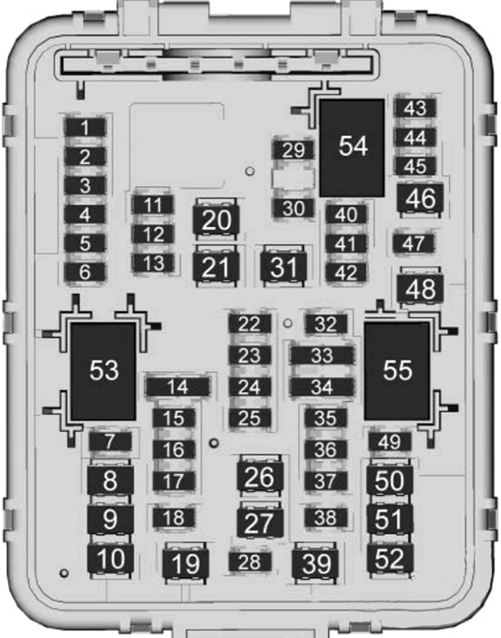
| № | Usage |
|---|---|
| F1 | Remote Function Actuator |
| F2 | Wireless Charging Module |
| F3 | Heated Seat Module Row 1 (Battery 1) |
| F4 | Memory Seat Module (MSM) Driver |
| F5 | – |
| F6 | – |
| F7 | Amplifier Auxiliary 2 |
| F8 | – |
| F9 | Search Engine Optimization Upfitter 2 |
| F10 | Motor Seatbelt Passenger |
| F11 | Power Folding Seat Row 2 |
| F12 | GBS |
| F13 | – |
| F14 | – |
| F15 | Heated Seat Module Row 1 (Battery 2) |
| F16 | Right Hand Cinch Latch |
| F17 | Memory Seat Module Passenger |
| F18 | Rear Wiper |
| F19 | Motor Seatbelt Driver |
| F20 | Rear Defogger |
| F21 | – |
| F22 | Rear HVAC Display Control |
| F23 | External Object Calculation Module |
| F24 | Amplifier Auxiliary 3 |
| F25 | OBS DET |
| F26 | Rear Drive Control Module |
| F27 | Amplifier Auxiliary 1 |
| F28 | Video Processing Module |
| F29 | – |
| F30 | – |
| F31 | Amplifier |
| F32 | – |
| F33 | Integrated Chassis Control Module |
| F34 | Heated Seat Module Row 2 |
| F35 | HFCR |
| F36 | Exterior Lighting Module |
| F37 | – |
| F38 | Power Slide Console |
| F39 | – |
| F40 | – |
| F41 | – |
| F42 | – |
| F43 | Universal Park Assist |
| F44 | – |
| F45 | Adaptive Forward Lighting/ Automatic Headlamp Leveling |
| F46 | Rear HVAC Blower Motor |
| F47 | Left Hand Cinch Latch |
| F48 | Power Seat Recline Module |
| F49 | Lift Glass |
| F50 | Driver Power Seat |
| F51 | Power Liftgate Module |
| F52 | Passenger Power Seat |
| Relays | |
| K53 | – |
| K54 | – |
| K55 | Lift Glass |
WARNING: Terminal and harness assignments for individual connectors will vary depending on vehicle equipment level, model, and market.