Holden Barina (TM; 2016 – 2018) – fuse box diagram
Year of production: 2016, 2017, 2018
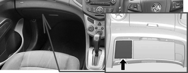
Passenger Compartment Fuse Box
Fuse Box Location
The interior fuse box is located in the glove box. To remove the cover: open the glove box; pull up on the lower edge of the cover.
Fuse Box Diagram

| № | Function |
|---|---|
| 1 | DLIS |
| 2 | Data link connector (DLC) |
| 3 | Airbag (SDM) |
| 4 | Tailgate (L/gate) |
| 5 | Power window rear |
| 6 | Body control module (BCM8) |
| 7 | Body control module (BCM7) |
| 8 | Body control module (BCM6) |
| 9 | Body control module (BCM5) |
| 10 | Body control module (BCM4) |
| 11 | Body control module (BCM3) |
| 12 | Body control module (BCM2) |
| 13 | Body control module (BCM1) |
| 14 | Instrument cluster (IPC) |
| 15 | Telematics |
| 16 | Rear parking assist (PAS) |
| 17 | Rain sensing wiper |
| 18 | Audio |
| 19 | Trailer1 |
| 20 | Lane departure warning / FCA |
| 21 | CGM |
| 22 | HVAC1 |
| 23 | Automatic headlamp leveling |
| 24 | Clutch |
| 25 | Instrument cluster / Automatic occupant sensing |
| 26 | Airbag / Run / Crank |
| 27 | Run relay |
| 28 | Liftgate release relay |
| 29 | Trailer2 |
| 30 | Clock spring |
| 31 | HVAC2 |
| 32 | – |
| 33 | Sunroof |
| 34 | Cigarette lighter |
| 35 | ESCL |
| 36 | – |
| 37 | – |
| 38 | Retained accessory power / Accessory |
| 39 | – |
| 40 | Front power window |
| 41 | – |
| 42 | IRAP ACCY |
| 43 | Battery connector |
| 44 | IRAP relay |
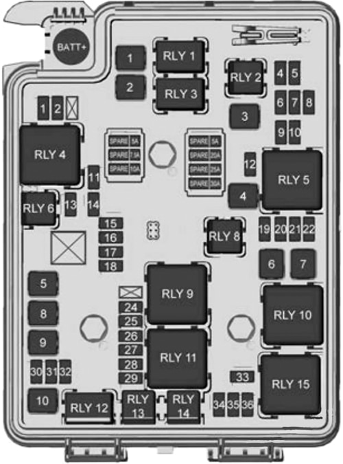
Engine Compartment Fuse Box
Fuse Box Location
Lift upwards and remove the cover.

Fuse Box Diagram
| № | Function |
|---|---|
| Mini Fuses | |
| 1 | ABS valve |
| 2 | Sunroof |
| 3 | – |
| 4 | Rear fog lamp |
| 5 | Outside rear view mirror (OSRVM) / Power window switch |
| 6 | Automatic occupant sensing (AOS) / ROS |
| 7 | Passive entry / Passive start (PEPS) |
| 8 | RVC |
| 9 | Rear wiper |
| 10 | – |
| 11 | Rear window defogger |
| 12 | ESCL |
| 13 | – / SAI valve |
| 14 | Heated outside rear view mirror (OSRVM HTD) |
| 15 | Front heated seats |
| 16 | Fuel system control module (FSCM1) |
| 17 | Canister vent |
| 18 | Washer |
| 19 | Fuel pump |
| 20 | Engine control module (ECM-5) |
| 21 | Fuel system control module (FSCM-2) /Levelling |
| 22 | TCM-1/ DC DC converter |
| 23 | – |
| 24 | Engine control module (ECM-1) |
| 25 | Coil |
| 26 | Engine control module (ECM-4) |
| 27 | Engine control module (ECM-3) |
| 28 | Engine control module (ECM-2) |
| 29 | Injector / Ignition coil |
| 30 | Engine control module (ECM) |
| 31 | A/C clutch |
| 32 | TCM |
| 33 | Horn |
| 34 | Front fog lamps |
| 35 | Left high-beam headlamp |
| 36 | Right high-beam headlamp |
| J-case fuses | |
| 1 | Front wiper |
| 2 | ABS pump |
| 3 | Blower |
| 4 | Run/Crank IEC |
| 5 | Power seat |
| 6 | Cooling fan K4 |
| 7 | Cooling fan K5 |
| 8 | SAI pump |
| 9 | EVP |
| 10 | Start |
| Relays | |
| 1 | Front wiper cont |
| 2 | Rear fog lamp |
| 3 | Front wiper speed |
| 4 | Rear defog |
| 5 | Run/Crank |
| 6 | – / SAI valve |
| 7 | – |
| 8 | Fuel pump |
| 9 | SAI pump |
| 10 | Cooling fan K3 |
| 11 | P/T |
| 12 | Start |
| 13 | AC clutch |
| 14 | High beam |
| 15 | Cooling fan K1 |
WARNING: Terminal and harness assignments for individual connectors will vary depending on vehicle equipment level, model, and market.