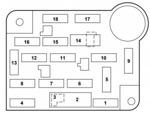
Mercury Grand Marquis Third Generation (1998 – 2002) – fuse box diagram
Year of production: 1998, 1999, 2000, 2001, 2002
Passenger compartment fuse panel

The fuse panel is located below and to the left of the steering wheel by the brake pedal. Remove the panel cover to access the fuses.
| Fuse/relay | Ampere rating [A] | Description |
| 1 | 15 | Brake Pedal Position (BPP) Switch, Speed Control, Multi-Function Switch |
| 2 | 30 | Wiper Control Module, Windshield Wiper Moto |
| 3 | — | Not used |
| 4 | 15 | Lighting Control Module, Main Light Switch |
| 5 | 15 | Backup Lamps, Variable Assist Power Steering (VAPS), Turn Signals, Air Suspension, Daytime Running Lamps, Electronic Day/Night Mirror, Shift Lock, EATC, Speed Chime Warning |
| 6 | 15 | Speed Control, Main Light Switch, Lighting Control Module, Clock |
| 7 | 25 | Powertrain Control Module (PCM) Power Diode, Ignition Coils |
| 8 | 15 | Lighting Control Module, Power Mirrors, PATS, Keyless Entry, Module, Clock Memory, Electronic Automatic Temperature Control (EATC), Power Windows, SecuriLock |
| 9 | 30 | Blower Motor, A/C-Heater Mode Switch |
| 10 | 10 | Air Bag Module |
| 11 | 5 | Radio |
| 12 | 18 CB | Lighting Control Module, Flash-to-Pass, Main Light Switch |
| 13 | 15 | Warning Lamps, Analog Cluster Gauges and Indicators, Electronic Automatic Transmission, Lighting Control Module |
| 14 | 20 CB | Window/Door Lock Control, Driver’s Door Module, One Touch Down |
| 15 | 10 | Anti-Lock Brakes, Instrument Cluster, Transmission Control Switch |
| 16 | 20 | Cigar Lighter; Auxiliary Power Point |
| 17 | 10 | Rear Defrost |
| 18 | 10 | Air Bag Module |
Power distribution box

The power distribution box is located in the engine compartment. The power distribution box contains high-current fuses that protect your vehicle’s main electrical systems from overloads.
| Fuse/relay | Ampere rating [A] | Description |
| 1 | 20* | Electric Fuel Pump Relay |
| 2 | 30* | Generator, Starter Relay, Fuses 15 and 18 |
| 3 | 25* | Radio, CD Changer, Subwoofer Amplifier |
| 4 | — | Not used |
| 5 | 15* | Horn Relay |
| 6 | 20* | DRL Module |
| 7 | 20 CB | Power Door Locks, Power Seats, Trunk Lid Release |
| 8 | 30** | Air Suspension System |
| 9 | 50** | See Fuses 5 and 9 |
| 10 | 50** | See Fuses 1, 2, 6, 7, 10, 11, 13 and Circuit Breaker 14 |
| 11 | 40** | See Fuses 4, 8, 16 and Circuit Breaker 12 |
| 12 | 30** | PCM Power Relay, PCM |
| 13 | 50** | High Speed Cooling Fan Relay |
| 14 | 40** | Rear Window Defrost Relay, Also see Fuse 17 |
| 15 | 50** | Anti-Lock Brake Module |
| 16 | — | Not used |
| 17 | 30 CB | Cooling Fan Relay |
| Relay 1 | — | Rear Defrost Relay |
| Relay 2 | — | Horn Relay |
| Relay 3 | — | Cooling Fan Relay |
| Relay 4 | — | Air Suspension Pump Relay |
| * Mini Fuses ** Maxi Fuses | ||
WARNING: Terminal and harness assignments for individual connectors will vary depending on vehicle equipment level, model, and market.
