Cadillac XT4 (2022) – fuse and relay box diagram
Year of production: 2022
Passenger Compartment
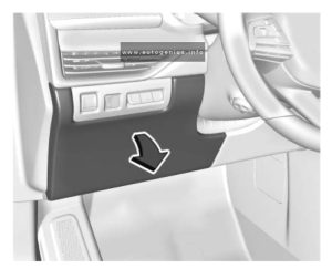
Fuse box Location
The fuse box is located on the driver’s side of the instrument panel behind the cover.

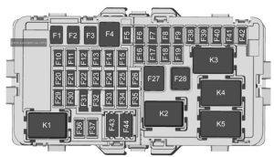
Fuse Box Diagram

Assignment of the fuses in the passenger compartment
| № | Usage |
|---|---|
| F1 | Left Power Window |
| F2 | Right Power Window |
| F3 | — |
| F4 | Direct Current to Direct Current Converter 2 |
| F5 | Auxiliary Power Outlet – Cargo |
| F6 | Heated Seat Battery 1 |
| F7 | Heated Seat Battery 2 |
| F8 | Body Control Module 3 – LED Headlamp Low Beam Right Control Signal, Right Front Turn Lamp Control Signal, Left Front Side Marker and Auxiliary Park, Left Rear Tail/Side Marker Control Signal, Left Daytime Running Lamps Control Signal |
| F9 | Electric Park Brake |
| F10 | Body Control Module 2 (Stop/Start) – Interior Lamps Control Signal, Door Handle Puddle Lamp (LED), Left Cornering Lamp, Right Cornering Lamp, Interior Lamps Control Signal, Backup Lamp Supply Voltage, License Plate Lamp Control Signal, Rear Closure Cargo Lamp Control Signal, Center High Mounted Stop Lamp LED Lamp Control Signal |
| F11 | — |
| F12 | — |
| F13 | — |
| F14 | — |
| F15 | Transmission Control Module (Stop/ Start) |
| F16 | Amplifier |
| F17 | |
| F18 | Video Processing Module |
| F19 | Power Steering Column |
| F20 | Body Control Module 6 – LED Backlight Control, Interior Lighting Inadvertent Load Control Signal, Fuel Door Lock Control Signal, LED Backlight Control Signal |
| F21 | Body Control Module 4 – LED Headlamp Low Beam Left Control Signal, Right Front Side Marker and Auxiliary Park, Right Rear Tail/ Side Marker Control Signal, Left Rear Stop Lamp Control Signal, Left Rear Stop/Turn Lamp Control Signal, Right DRL Control Signal |
| F22 | Body Control Module 7 – Right Rear Stop Lamp Control Signal, Right Rear Stop/ Turn Lamp Control Signal, Left Front Turn Lamp Control Signal, Right Rear Turn Control Signal |
| F23 | — |
| F24 | Airbag |
| F25 | Data Link Connector |
| F26 | — |
| F27 | — |
| F28 | — |
| F29 | Body Control Module 8 – Internal Driver/Fuel Door Unlock Relay Control Signal, Internal Non-Driver Door Lock Relay Control Signal, Internal All Door Unlock Relay Control Signal |
| F30 | Overhead Console |
| F31 | Steering Wheel Controls |
| F32 | — |
| F33 | Heating Ventilation and Air Conditioning Control Module |
| F34 | Central Gateway Module |
| F35 | Heated Seat Switch/Hazard Switch |
| F36 | Wireless Charger Module/USB Charge Port |
| F37 | — |
| F38 | OnStar |
| F39 | Shifter Interface Board/Center Stack/Head Up Display/ Instrument Panel Cluster/HVAC Display |
| F40 | Long Range Radar Sensor/ Ultrasonic Park Assist Module/Camera Module/External Object Calculating Module/ Side Blind Zone Alert Modules/Front Camera Module |
| F41 | Body Control Module 1 (Stop/Start) – LED Indicator Lighting Control, Accessory LED Control, Run-Start LED Control, Ambient Lighting LED Control 2, Liftgate Latch Motor Control Signal, Rear Wiper Control Signal, High Beam Lamp Control (Direct Drive), Rear Fog LED Lamp Control Signal, Windshield Washer Pump Motor Control Signal, Run/Crank Relay Control Signal, ECM/TCM ACC Wakeup Control Signal, Left Rear Turn Control Signal, Rear Wiper Wash Pump Control Signal, Brake Pedal Apply Signal |
| F42 | Radio |
| F43 | Console Auxiliary Power Outlet (Circuit Breaker) |
| F44 | Front Console Auxiliary Power Outlet |
| Relay | |
| K1 | — |
| K2 | Retained Accessory Power |
| K3 | — |
| K4 | — |
| K5 | — |
| K5 | Not Used |
Engine Compartment
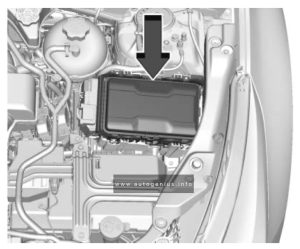
Fuse Box Location
The instrument panel fuse block is in the center console between the driver and passenger seats.

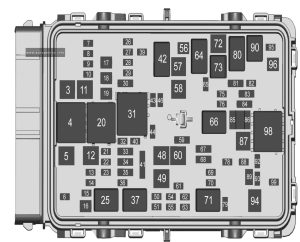
Fuse Box Diagram

Assignment of the fuses in the engine compartment
| № | Usage |
|---|---|
| 3 | Electronic Brake Control Module |
| 5 | Not Used |
| 6 | Spare |
| 7 | Left Trailer Stop/Turn Lamp |
| 8 | Memory Seat Module, Driver and Passenger |
| 9 | — |
| 10 | Semi-active Damping System/Spare |
| 11 | Direct Current to Direct Current Converter 1 |
| 12 | Rear Window Defogger |
| 13 | Outside Rear View Mirrors Defogger |
| 14 | — |
| 15 | Passive Entry Passive Start Module |
| 16 | Front Wiper |
| 17 | Passenger Power Seat |
| 18 | Power Liftgate |
| 19 | Driver Power Seat/ Memory Seat Module/ Driver Seat Massage Control |
| 21 | Power Sunroof |
| 22 | — |
| 23 | — |
| 26 | Transmission Control Module/Ignition |
| 27 | Inside Rear View Mirror, Shifter Interface Board Module Run/Crank, Central Gateway Module Run/Crank, Heating Ventilation and Air Conditioning Control Module Run/Crank ignition 3 |
| 28 | Rear Wiper |
| 29 | — |
| 30 | Fuel Tank Zone Module Run/Crank, Direct Current to Direct Current Transformer Run/Crank, Electronic Brake Control Module Run/Crank, Instrument Panel Cluster Run/Crank |
| 32 | Rear Drive Control Module 1 |
| 33 | Front Heated Seat Power 2 |
| 34 | Liftgate Module / Front Window Switches |
| 35 | — |
| 36 | Fuel Tank Zone Module |
| 39 | Driver Seat Massage / Passenger Seat Massage |
| 40 | — |
| 41 | — |
| 43 | Heated Steering Wheel |
| 44 | Front Heated Seat Power Feed 1 / Front Vented Seats/ Rear Heated Seats |
| 46 | Engine Control Module Ignition |
| 48 | Rear Drive Control Module 2 |
| 49 | Heating Ventilation and Air Conditioning Control Blower Motor |
| 50 | Spare |
| 51 | Spare |
| 54 | Spare |
| 55 | Spare |
| 56 | Starter Motor |
| 57 | — |
| 58 | — |
| 59 | High Beam Headlamps |
| 60 | — |
| 61 | Spare |
| 62 | Spare |
| 63 | Spare |
| 65 | Air Conditioning Clutch |
| 67 | Spare |
| 68 | Spare |
| 69 | — |
| 70 | Trailer Park Lamp |
| — | |
| 72 | Starter Pinion |
| 75 | Engine Control Module Main |
| 76 | Powertrain Off Engine, Engine Control Module Power Train Ignition 1 |
| 78 | Horn |
| 79 | Front and Rear Washer Pump |
| 81 | Engine Control Module Battery/Spare |
| 82 | — |
| 83 | Ignition Coils |
| 84 | Canister Purge Solenoid / Step Cam Exhaust Solenoid Cylinder 2 and 3 / Step Cam Intake Cylinder Solenoids / Turbo Bypass Solenoid / Oxygen Sensor (Pre) / O2 Heater / Oxygen Heated Sensor / Mass Airflow / Inlet Air Temperature / Throttle Inlet Absolute Pressure / Coolant Flow Control Valve |
| 85 | Shunt |
| 86 | Shunt |
| 87 | — |
| 88 | Aeroshutter |
| 89 | — |
| 92 | — |
| 93 | Canister Vent Solenoid |
| 95 | — |
| 96 | — |
| 99 | — |
| Relays | |
| 20 | Rear Defogger / Outside Rear View Mirrors Defogger |
| 25 | Front Wiper Control |
| 31 | Run/ Crank |
| 37 | Front Wiper Speed |
| 42 | — |
| 64 | STRTR MTR, |
| 66 | Powertrain |
| 71 | Trailer Park Lamps |
| 73 | Air Conditioning Controls |
| 80 | Starter Pinion |
| 90 | — |
| 94 | — |
| 98 | — |
WARNING: Terminal and harness assignments for individual connectors will vary depending on vehicle equipment level, model, and market.
