Chery Tiggo 5 (T21; 2013 – 2015) – fuse and relay box diagram
Year of production: 2013, 2014, 2015
Passenger Compartment Fuse Panel
Fuse Box A
Fuse Box Location
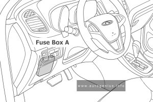
Instrument panel fuse and relay box A is located on the lower left side of instrument panel.
Fuse Box Diagram
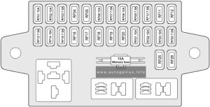
Assignment of the fuses in the instrument panel fuse and relay box A
| № | Description |
|---|---|
| RF01 | Reversing Radar |
| RF02 | SPORT Switch Backlight (for CVT Model) / Headlight Leveling Dial |
| RF03 | Back-up Light Relay Coil (for CVT Model) |
| RF04 | – |
| RF05 | – |
| RF06 | Yaw Sensor / Steering Angle Sensor / Instrument Cluster / Front Passenger Seat Belt Reminder Light / Diagnosis Connector / Engine Immobilizer / ESP Indication |
| RF07 | BCM/EPS/PEPS |
| RF08 | Airbag |
| RF09 | Brake Switch |
| RF10 | A/C Control Panel |
| RF11 | – |
| RF12 | – |
| RF13 | Relay Coils of Rear Defroster, Blower, Seat Heater / Audio System / BCM |
| RF14 | Cigarette Lighter |
| RF15 | Outside Rear View Mirror Adjustment Switch / Sunroof Switch |
| RF16 | – |
| RF17 | – |
| RF18 | – |
| RF19 | – |
| RF20 | – |
| RF21 | Automatic A/C Control Panel |
| RF22 | Audio System |
| RF23 | Instrument Cluster / Diagnosis Connector |
| RF24 | Key Switch |
| RF25 | – |
| RF26 | – |
Fuse Box B
Fuse Box Location
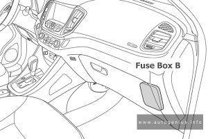
Instrument panel fuse and relay box B is located on the lower right side of instrument panel.
Fuse Box Diagram
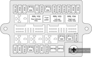
Assignment of the fuses in the instrument panel fuse and relay box B
| № | Description |
|---|---|
| RF27 | Spare |
| RF28 | – |
| RF29 | – |
| RF30 | IP Fuse and Relay Box A |
| RF31 | – |
| RF32 | Power Seat Adjustment |
| RF33 | Rear Defroster |
| RF34 | Left Seat Heater |
| RF35 | Brake Light Switch |
| RF36 | Reserve |
| RF37 | Right Seat Heater |
| RF38 | – |
| RF39 | – |
| RF40 | Right Window Jam Protection |
| RF41 | Left Window Jam Protection |
| RF42 | Outside Rear View Mirror Heating / Defrosting Feedback Signal |
| RF43 | – |
| RF44 | – |
| RF45 | Backup Power Supply |
| RF46 | Ignition Switch |
| RF47 | PEPS |
| RF48 | – |
| RF49 | Sunroof |
| RF50 | – |
| RF51 | – |
Engine Compartment Fuse Panel
Fuse Box Location
Engine compartment fuse and relay box is located on the left side of engine compartment and the rear side of left headlight.
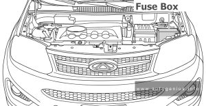
Fuse Box Diagram
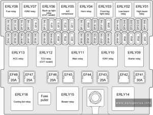
Assignment of the fuses in the engine compartment
| № | Description |
|---|---|
| EF01 | Right Headlight High Beam |
| EF02 | Left Headlight High Beam |
| EF03 | Right Headlight Low Beam |
| EF04 | Left Headlight Low Beam |
| EF05 | Front Fog Light |
| EF06 | – |
| EF07 | Ignition Coil |
| EF08 | Injector / Camshaft Timing |
| EF09 | – |
| EF10 | A/C Compressor |
| EF11 | – |
| EF12 | – |
| EF13 | – |
| EF14 | – |
| EF15 | IGN2 |
| EF16 | – |
| EF17 | ECM/TCU (for CVT Model) |
| EF18 | Spare |
| EF19 | TCU (for CVT Model)/ECM |
| EF20 | Spare |
| EF21 | – |
| EF22 | – |
| EF23 | – |
| EF24 | – |
| EF25 | Horn |
| EF26 | Spare |
| EF27 | Air Flow Meter / Canister |
| EF28 | Back-up Light Switch (for MT Model) |
| EF29 | Alternator Excitation |
| EF30 | Back-up Light / Reversing Radar (for CVT Model) |
| EF31 | – |
| EF32 | – |
| EF33 | – |
| EF34 | IGN Power Supply |
| EF35 | Fuel Pump |
| EF36 | ABS/ESP |
| EF37 | Spare |
| EF38 | Fuel Pump Relay Coil / Fan Relay Coil |
| EF39 | Oxygen Sensor |
| EF40 | ECM |
| EF41 | Starter |
| EF42 | – |
| EF43 | IGN1 |
| EF44 | – |
| EF45 | – |
| EF46 | TCU (for CVT Model) |
| EF47 | ABS/ESP |
| EF48 | ACC |
| EF38 | ECU & DCT 30+ |
| EF39 | Wiper RLY |
| EF40 | – |
| EF41 | Seat Heater |
| EF42 | A/C clutch |
| EF43 | – |
| EF44 | BCM 4 |
| EF45 | Sunroof |
| EF46 | Memory Fuse |
| EF47 | IP Fuse Box power |
| EF48 | EPS power |
| EF49 | ALT power |
| EF50 | Cooling Fan |
| EF52 | FW Heater 2 |
| EF53 | FW Heater 1 |
WARNING: Terminal and harness assignments for individual connectors will vary depending on vehicle equipment level, model, and market.
