Ford E-Series E-150 E150 E 150 (2009) – fuse box diagram
Year of production: 2009
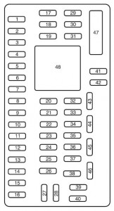
Passenger compartment fuse panel
The fuse panel is located to the left of the brake pedal and mounted onto the lower left cowl panel.

| Fuse/relay location | Ampere rating [A] | Protected circuit |
| 1 | 30 | Not used (spare) |
| 2 | 15 | Not used (spare) |
| 3 | 15 | Not used (spare) |
| 4 | 30 | Not used (spare) |
| 5 | 10 | SPDJB/Brake shift interlock |
| 6 | 20 | Turn signal, Hazard, Stop lamps |
| 7 | 10 | Left low beam |
| 8 | 10 | Right low beam |
| 9 | 15 | Courtesy lamps |
| 10 | 15 | Switch illumination |
| 11 | 10 | Not used (spare) |
| 12 | 7,5 | Not used (spare) |
| 13 | 5 | Mirrors |
| 14 | 10 | Not used (spare) |
| 15 | 10 | Not used (spare) |
| 16 | 15 | Not used (spare) |
| 17 | 20 | Door locks |
| 18 | 20 | Not used (spare) |
| 19 | 25 | Not used (spare) |
| 20 | 15 | Diagnostic connector |
| 21 | 15 | Not used (spare) |
| 22 | 15 | Park lamps, License plate lamps |
| 23 | 15 | High beams |
| 24 | 20 | Horn |
| 25 | 10 | Demand lighting |
| 26 | 10 | Cluster |
| 27 | 20 | Ignition switch feed |
| 28 | 5 | Audio mute (start) |
| 29 | 5 | Cluster |
| 30 | 5 | Not used (spare) |
| 31 | 10 | Not used (spare) |
| 32 | 10 | Restraints module |
| 33 | 10 | Trailer Brake Controller |
| 34 | 5 | Not used (spare) |
| 35 | 10 | Reverse park aid, Rear video camera, Cutaway run/start |
| 36 | 5 | PATS RF module |
| 37 | 10 | Climate control, Stripped chassis IP #1 run/start |
| 38 | 20 | Not used (spare) |
| 39 | 20 | Radio, Navigation |
| 40 | 20 | Amplifier |
| 41 | 15 | Radio, Switch illumination, Reverse camera mirror |
| 42 | 10 | Upfitter switch |
| 43 | 10 | Overhead console, Stripped chassis IP1 |
| 44 | 10 | Auxiliary Battery Relay |
| 45 | 5 | Wipers, Stripped chassis Engine connector 3 |
| 46 | 7,5 | PADI |
| 47 | 30 circuit breaker |
Windows accessory delay |
| 48 | Relay | Delayed accessory |
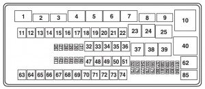
Power distribution box
The power distribution box is located in the engine compartment. The power distribution box contains high-current fuses that protect your vehicle’s main electrical systems from overloads.

| Fuse/relay location | Ampere rating [A] | Protected Circuits |
| 1 | Micro Relay | Powertrain Control Module (PCM) |
| 2 | Micro Relay | Starter solenoid |
| 3 | Micro Relay | Wiper |
| 4 | Micro Relay | Trailer tow battery charge |
| 5 | Micro Relay | Fuel pump |
| 6 | Micro Relay | Trailer tow park lamp |
| 7 | Micro Relay | Upfitter #4 |
| 8 | Micro Relay | Upfitter #3 |
| 9 | Micro Relay | Modified vehicle and stripped chassis run/start |
| 10 | ISO | IDM relay (Diesel engine only) |
| 11 | — | Not used |
| 12 | 40** | Modified vehicle and stripped chassis run/start |
| 13 | 30** | Starter solenoid relay |
| 14 | 40** | Run start relay |
| 15 | 40** | Modified vehicle and stripped chassis battery |
| 16 | 50** | Auxiliary A/C blower |
| 17 | 50** | Auxiliary battery feed, Trailer tow battery charge, trailer tow park feed |
| 18 | 30** | Electric trailer brake, Trailer brake controller |
| 19 | 30** | Upfitter #1 |
| 20 | 30** | Upfitter #2 |
| 21 | 50** | IDM relay (diesel engine only) |
| 22 | — | Not used |
| 23 | G8VA relay | A/C clutch |
| 24 | G8VA relay | Horn relay (Stripped chassis) |
| 25 | Micro relay | Run/start |
| 26 | — | Not used |
| 27 | — | Not used |
| 28 | 20* | Back up lamp |
| 29 | 10* | A/C clutch |
| 30 | 10* | BOO switch |
| 31 | 10* | Cluster battery (stripped chassis only), IDM coil (diesel engine only) |
| 32 | 50** | Blower motor |
| 33 | 40** | ABS pump |
| 34 | 20** | Stripped chassis horn |
| 35 | 40** | PCM relay |
| 36 | 20** | Ignition switch (Stripped chassis only) |
| 37 | G8VA relay | Trailer tow stop/LH turn signal |
| 38 | G8VA relay | Trailer tow stop/RH turn signal |
| 39 | G8VA relay | Back up lamp |
| 40 | ISO relay | Blower motor |
| 41 | 10* | Charging (diesel engine only) |
| 42 | 15 | Diagnostic connector (stripped chassis) |
| 43 | 20* | Fuel pump |
| 44 | 10* | Upfitter #3 |
| 45 | 15* | Upfitter #4 |
| 46 | 10* | PCM keep alive power, Canister vent, PCM relay coil |
| 47 | 40** | ABS coil |
| 48 | 20** | Trailer tow stop lamp/turn signal |
| 49 | 30** | Wiper motor |
| 50 | — | Not used |
| 51 | 20** | Cutaway |
| 52 | 10* | Stripped chassis and modified vehicle run/start relay coil |
| 53 | 10* | ABS run/start feed |
| 54 | 10* | Fuel pump relay coil (gas engine only) |
| 55 | 10* | ECM (diesel engine only) |
| 56 | 20* | DFCM (diesel engine only) |
| 57 | 20* | Trailer tow park lamp |
| 58 | 15* | Trailer tow backup |
| 59 | — | Not used |
| 60 | — | One Touch Integrated Start (OTIS) (diode) |
| 61 | — | Auxiliary battery (diode) |
| 62 | Micro relay | Upfitter #2 |
| 63 | 30** | Trailer tow battery charge |
| 64 | — | Not used |
| 65 | 20** | Power point 2 (glove box) |
| 66 | 20** | Power point 3 (left-hand B-pillar) |
| 67 | 20** | Power point 1 (instrument panel) |
| 68 | 50** | Modified vehicle |
| 69 | — | Not used |
| 70 | 30** | Stripped chassis |
| 71 | — | Not used |
| 72 | 20** | Cigar lighter |
| 73 | — | Not used |
| 74 | 30* | Power seat |
| 75 | 20* | VPWR 1, PCM power |
| 76 | 20* | VPWR 2, PCM mil |
| 77 | 10* | VPWR 3, PCM non mil |
| 78 | 15* | VPWR 4 (gas engine only), Ignition coil (diesel engine only), Fuel pump relay coil |
| 79 | 10* | VPWR 5, Transmission |
| 80 | 10* | Cluster run/start (stripped chassis only) |
| 81 | 15* | IDM logic (diesel engine only) |
| 82 | — | Not used |
| 83 | — | Fuel pump (diode) |
| 84 | — | Not used |
| 85 | Micro relay | Upfitter #1 |
| * Mini fuses
** A1 fuses |
||
WARNING: Terminal and harness assignments for individual connectors will vary depending on vehicle equipment level, model, and market.
