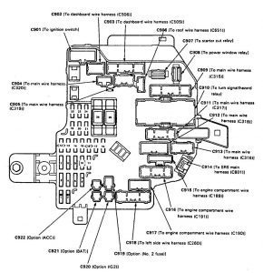
Acura Legend (1994 – 1995) – fuse box diagram
Year of productions: 1994, 1995
Under-dash fuse box
Under-dash fuse box is located behind left kick panel

| Number | A | Component or Citcuit Protected |
| 1 | — | Option connector: C921 |
| 2 | — | Option connector: C919 |
| 3 | 15 | ASS pump motor relay, ABS control unit, ABS front and rear failsale relays, ABS inspection connector, A/C compressor clutch, A/C compressor clutch relay, Fan control unit, Radiator fan relay, Rear window defogger relay, Rear window defogger indicator fight, (option C920) |
| 4 | 10 | Stereo radio/cassette piayer, Cigarette lighter relay, Cellular phone, (option C922) |
| 5 | 20 | PGM·FI main relay |
| 6 | — | — |
| 7 | 10 | SRS unit |
| 8 | 20 | Seat belt presenter, Power door closer control unit |
| 9 | 15 | Cigarette lighter |
| 10 | 15 | Heated seat (seat backs, cushions. and switches) |
| 11 | 20 | A/C compressor clutch relay |
| 12 | 7,5 | Daytime running lights control unit |
| 13 | 7,5 | Integrated control unit, Clock, Gauges, Back-up lights, Turn signal/hazard relay, Shift lock solenoid, Seat belt tension control |
| 14 | 7,5 | Powertrein or engine control module, PGM-FI main relay, Gauge assembly (bulb check circuit) |
| 15 | 7,5 | Powertraln or engine control module, Radiator fan control module, Security control unit, Driving position memory system (OPMS), Charging system |
| 16 | 20 | Daytime running lights control unit |
| 17 | 20 | Power window control unit |
| 18 | 20 | Passenger’s power window motor |
| 19 | 7,5 | Climate control unit, Heater control panel, Seat heater relay, Healed minors, Recirculation control motor, Blower motor relay, Blower motor high relay, Power mirror actuators, Mode control motor (manual A/C) |
| 20 | 7,5 | Cruise control unit. Radiator fan control module, Security control unit, Driving position memory system (DPMS) |
| 21 | — | — |
| 22 | 20 | PGM·FI, SRS unit, Charging system, Traction control system (TCS), Vehicle speed sensor (VSS) |
| 23 | 7,5 | Wildshield wiper relays, Washer motor, Moonroof relays |
| 24 | — | — |
| 25 | 30 | PGM·FI main relay, ignition coils, noise condenser |
| 26 | 30 | Windshield wiper motor |
Engine compartment fuse box
Under-hood relay/fuse box is located on the left side of engine compartment.
| Number | A | Component or Citcuit Protected |
| 31 | 120 | Main banery fuse |
| 32 | 50 | ABS pump motor, Fuse 38 |
| 33 | 40 | Rear window defogger |
| 34 | 50 | Under-dash fuse/relay box (BAT) |
| 35 | 50 | Ignition switch (BAT) |
| 36 | 40 | Power windows |
| 37 | 40 | Blower motor |
| 38 | 7,5 | ABS control unit |
| 39 | 20 | Hom relay, Left and right horns, Key Interlock solenoid, Security Indicator, ABS control unit, Cruise control unit, Powetrain or engine control module, Brake lights, Trailer fighting connector |
| 40 | 15 | Tum signal/hazard relay, Hazard warning lights |
| 41 | 15 | ABS control unit (B1) |
| 42 | 15 | ABS control unit (B2), TCS control unit |
| 43 | 15 | ABS control unit (B3) |
| 44 | 20 | Power door lock, control unit, Trunk opener solenoid |
| 45 | 20 | Right headnght. Daytime running lights control unit (Canada) |
| 46 | 20 | Left headlight, High beam indicator light, Daytime running lights control(Canada) |
| 47 | 20 | Radiator fan motor |
| 48 | 10 | Left taillight, Trailer lighting connector |
| 49 | 15 | Front parldng lights, Vanity mirror lights, License plate lights, Right taillights, Integrated control unit, Rear spot lights, Gauge lights, Stereo radio/cassette player, Courtesy light controller (LS and GS), Dash lights brightness control unit, Dash lights |
| 50 | 20 | Condenser fan motor |
| 51 | 30 | Moonroof motor |
| 52 | 30 | Front passenger’s power seat motors (slide-recline) |
| 53 | 15 | Traction control system (TCS) |
| 54 | 20 | Amplifier |
| 55 | 30 | Power seat control unit |
| 56 | 7,5 | Climate control unit, Clock, Stereo radio/cassette player, Power antenna motor, car telephone system, Integrated control unit |
| 57 | 15 | Front courtesy lights, Rear courtesy lights, Trunk light, Footwell lights, Ignition key light, Front and rear celing lights, Trailer lighting connector, Ceiling light relay, Front spot lights |
| 58 | 30 | Steering oolurnn control unit |
WARNING: Terminal and harness assignments for individual connectors will vary depending on vehicle equipment level, model, and market.