Acura TL (2006) – fuse box diagram
Year of production: 2006
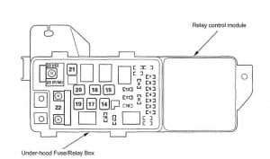
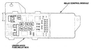
Under-hood Fuse/Relay Box
| Fuse | Fuse name | [A] | Component or cricuit protected |
| 1 | L-H/L LO | 15 | Left headlight (HID unit) |
| 2 | RR DEFROSTER COIL | 30 | Relay control module |
| 3 | L-H/L HI | 7,5 | Left headlight (High/low beam switching solenoid) |
| 4 | SMALL LIGHT | 10 | Taillight relay |
| 5 | R-H/L HI | 7,5 | Right headlight (High/low beam switching solenoid) |
| 6 | R-H/L LO | 15 | Right headlight (HID unit) |
| 7 | BACK UP | 7,5 | Relay control module |
| 8 | Fl ECU | 15 | PGM-FI main relay 1, DLC |
| 9 | CONDENSER FAN | 30 | A/C condenser fan relay |
| 10 | FR FOG | 20 | Fog light relay (USA) |
| 15 | DRL relay (Canada) | ||
| 11 | COOLING FAN | 30 | Radiator fan relay |
| 12 | MG CLUTCH | 7,5 | A/C compressor clutch relay |
| 13 | HORN, STOP | 20 | Brake pedal position switch, Horn relay |
| 14 | RR DEFROSTER | 40 | Rear window defogger relay |
| 15 | BACK UP, ACC | 40 | Fuse 7 in under-hood fuse/relay box, Fuses 5, 6, 7, 8, and 9 in under-dash fuse/relay box |
| 16 | HAZARD | 15 | Hazard warning switch, Turn signal/hazard relay |
| 17 | VSA MOTOR | 30 | VSA modulator-control unit |
| 18 | VSA | 40 | VSA modulator-control unit |
| 19 | Fl ECU | 40 | Fuses 1, 2, 3, and 4 in under-dash fuse/relay box |
| 20 | POWER SEAT | 40 | Fuses 12, 13, 14, 15, 16, and 17 in under-dash fuse/relay box |
| 21 | HEATER MOTOR | 40 | Blower motor relay |
| 22 | BATTERY | 120 | Alternator, Battery, Power distribution |
| — | — | — | |
| 23 | +B IG1 MAIN | 50 | Fuse 33 in under-dash fuse/relay box, Ignition switch |
| POWER WINDOW | 50 | Fuses 24, 25, 26, 27 and 28 in under-dash fuse/relay box, Power window relay |
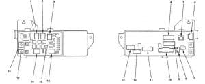
| Ref | Socket | Cavities | Connects to |
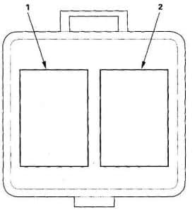
| 1 | Blower motor relay | 4 | |
| 2 | A/C compressor clutch relay | 4 | |
| 3 | Rear window defogger relay | 4 | |
| 4 | D | 9 | Engine compartment wire harness (left branch) |
| 5 | A (ELD unit) | 3 | Engine compartment wire harness (left branch) |
| 6 | G | 2 | Engine compartment wire harness (left branch) |
| 7 | B | 1 | — |
| 8 | C | 2 | Engine compartment wire harness (left branch) |
| 9 | E | 16 | Engine compartment wire harness (left branch) |
| 10 | F | 20 | Front engine compartment wire harness |
| 11 | H | 14 | Front engine compartment wire harness |
| 12 | J | 5 | Engine compartment wire harness (left branch) |
| 13 | K | 10 | Engine compartment wire harness (left branch) |
| 14 | Radiator fan relay | 4 | |
| 15 | A/C diode A | 2 | |
| 16 | A/C Condenser Fan Relay | 4 | |
| 17 | T101 | Starter cable | |
| 18 | T102 | Engine wire harness |
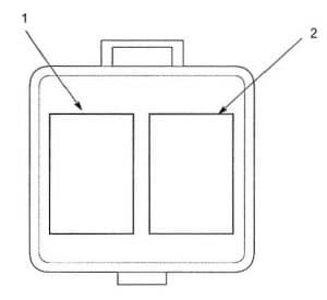
Connector-to-Multi-Relay Box Index
| Ref | Socket | Cavites | Connects to |
| 1 | Fog Light Relay (USA) | 4 | Front engine compartment wire harness |
| 1 | DRL relay (Canada) | 4 | Front engine compartment wire harness |
| 2 | Fan control relay | 5 | Front engine compartment wire harness |
Under-hood Fuse/Relay Box
| Socket | Ref | Terminal | Connects to |
| A/C compressor clutch relay | 2 | 4 | |
| A/C condenser fan relay | 15 | 4 | |
| A (ELD unit) | 5 | 3 | Engine compartment wire harness |
| B | 7 | — | |
| Blower motor relay | 1 | 4 | |
| C | 8 | 2 | Engine compartment wire harness |
| D | 4 | 9 | Engine compartment wire harness |
| E | 9 | 16 | Engine compartment wire harness |
| F | 10 | 20 | Front engine compartment wire harness |
| G | 6 | 2 | Engine compartment wire harness |
| H | 11 | 14 | Front engine compartment wire harness |
| J | 12 | 5 | Engine compartment wire harness |
| K | 13 | 10 | Engine compartment wire harness |
| Radiator fan relay | 14 | 4 | |
| Rear window defogger relay | 3 | 4 | |
| T101 | 17 | Starter cable | |
| T102 | 16 | Engine wire harness |
Under-hood Multi-relay Box
| Socket | Ref | Terminal | Connects to |
| Fog lights/daytime running lights relay | 1 | 4 | Front engine compartment wire harness |
| Fan control relav | 2 | 5 | Front engine compartment wire harness |
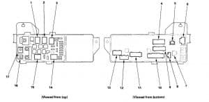
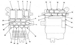
Under-dash Fuse/Relay Box
| Socket | Ref | Terminal | Connects to |
| A | 6 | 6 | Dashboard wire harness |
| Accessory power socket relay | 19 | 4 | |
| A/F sensor relay | 20 | 4 | |
| B | 12 | 6 | Engine compartment wire harness |
| C | 11 | 12 | Engine compartment wire harness |
| D | 13 | 17 | Engine compartment wire harness |
| E | 8 | 16 | Floor wire harness |
| F | 9 | 14 | Floor wire harness |
| G | 14 | 6 | Floor wire harness |
| H | 15 | 14 | Floor wire harness |
| Ignition coil relay | 23 | 4 | |
| J | 27 | 21 | Driver’s door subharness |
| K | 26 | 12 | Driver’s door subharness |
| M | 25 | 3 | MICS service check connector |
| N | 2 | 45 | Dashboard wire harness |
| P (MICU) | 17 | 30 | Dashboard wire harness |
| PGM-FI main relay 1 | 21 | 4 | |
| PGM-FI main relay 2 | 24 | 4 | |
| Power window relay | 22 | 4 | |
| Q (MICU) | 16 | 14 | Dashboard wire harness |
| R (MES connector) | 3 | 2 | Dashboard wire harness |
| S | 5 | 2 | Dashboard wire harness |
| Starter cut relay | 18 | 4 | |
| T | 7 | 6 | Optional connector |
| Turn signal/hazard relay | 4 | 6 | |
| W | 10 | 5 | Roof wire harness |
| X | 1 | 39 | Dashboard wire harness |
Under-hood Fuse/Relay Box
| Fuse | [A] | Wire color | Components or circuit protected |
| 1 | 15 | WHT/GRN | Throttle actuator control module (via throttle actuator control module relay) |
| 2 | 15 | Fuse/relay box socket |
Ignition coil (IG) relay |
| BLK/WHT | Ignition coils Ma ianition coil relavl_ | ||
| 3 | — | — | — |
| 4 | 15 | WHT/BLK | A/F sensors (front and rear bank), Secondarv H02S (front and rear bank) |
| 5 | 20 | WHT | Audio amplifier Audio unit |
| 6 | 7,5 | GRY/BLU | Courtesy lights,HandsFreelink control unit, Ignition key light, Keyless receiver unit, Map lights, Roof console, Trunk liaht Vanitv mirror Jiahts |
| 7 | 7,5 | WHT/RED | Audio-HVAC display modtJie, Clock (without navigation), Combination switch control unit, Gauge control module, Front passenger’s power window switch/control unit, Immobilizer control unitreceiver, Navigation unit, Security indicator, Power window master switch, Power mirror control unit, XM receiver unit |
| Fuse/relay box socket |
Multiplex integrated control unit (MICU) | ||
| 8 | 20 | WHT | Trunk lid opener solenoid |
| Fuse/relay box socket |
Multiplex integrated control unit (MICU) | ||
| 9 | 15 | WHT/RED | Front accessory oower socket Rear accessorv power socket |
| 10 | 7,5 | WHT | OPDS unit SRS unit |
| 11 | 30 | GRN | Windshield wiper motor |
| 12 | 7,5 | RED/WHT | TPMS control unit (’06 model) |
| 13 | 20 | RED/WHT | Front passenaer’s power seet recline motor |
| 14 | 20 | WHT/BLU | Driver’s power saat control unit |
| 15 | 20 | RED/BLK | Seat heaters and seat heater, switches indicator light |
| 16 | 20 | WHT/RED | Driver’s power seat control unit Driver’s seat lumbar motor |
| 17 | 20 | WHT/GRN | Front oassenaer’s oower seat slide motor |
| 18 | 15 | BLK/YEL | Alternator, ECM!PCM (via brake pedal position switc), ELD unit, Engine mount control solenoid valve, EVAP canister purge valve, EVAP.vent shut solenoid valve, Reverse lockout sotenoid (M/T), VSA modulator-control unit |
| 19 | 15 | BLK/GRN | ECM/PCM Immobilizer control unit-receiver |
| YEL/GRN | Fuel pump (via PGM-FI main relav 2) | ||
| 20 | 7,5*1 | YEL/GRN | Automatic dimming inside mirror, Power mirror control unit, Windshield washer motor |
| 15*2 | |||
| 21 | 7,5 | YEL | Back-up lights, Clock twithout navigation), Combination switch control unit, Gauge control module, Keyless receiver unit, Multiplex integrated control unit (MICI)), Relay controt module, Shift lock relay (A/T), Seat belt tension reducers TPMS control unit |
| 22 | 10 | WHT/RED | SRS unit |
| 23 | 7,5 | YEL/WHT | Radiator fan relay |
| Fuse/relay box socket |
A/F sensor relay | ||
| 24 | 20 | YEL/RED | Left rear power window motor |
| 25 | 20 | YEL/BLU | Right rear power window motor |
| 26 | 30 | GRN/BLK | Front passenger’s power window motor |
| 27 | 30 | GRN/WHT | Driver’s power window motor |
| 28 | 20 | GRN | Moonroof control unit |
| 29 | — | — | — |
| 30 | 7,5 | BLK/YEL | A/C compressor clutch relay, Blower motor relay, Climate control unit, Condenser fan relay, Power mirror actuators and defoggers, Radiator fan relay, Recuration control motor, Rear window defogger relay |
| 31 | — | — | — |
| 32 | 7,5 | YEL/RED | Audio unit, Audio-HVAC display module, Navigation unit, Shift lock solenoid (A/T), HandsFreelink control unit |
| Fuse/ relay box socket |
Accessory power socket relay, Multiplex integrated control unit (MICU) | ||
| 33 | — | — | — |
| * 1: ’04-05 models * 2: ’06 model |
|||
WARNING: Terminal and harness assignments for individual connectors will vary depending on vehicle equipment level, model, and market.

