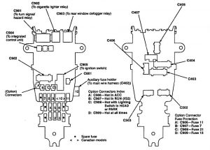
Acura Vigor (1992) – fuse box diagram
Year of production: 1992
Passenger compartment fuse box

| Position | Fuse rating [A] | Protected component |
| 1 | 10 | Vehicle speed sensor, Back up lights, Shift position sensor, Gauge assembly, Integrated control unit, Clock |
| 2 | 15 | PGM-FI, Fan timer unit, ELD, Alternator, SRS, Gauge assembly |
| 3 | 10 | SRS control unit |
| 4 | 7,5 | Automatic transmission controls, Security system. Cruise control |
| 5 | 10 | Shift lock solenoid, Windshield wipers, Sunroof |
| 6 | 30 | Windshield wipers, Integrated control unit |
| 7 | 7,5 | ABS, A/C |
| 8 | 7,5 | Heated seats (Canada). Fan timer unit, A/C compressor clutch re1lay, Rear window defogger, Power door mirrors |
| 9 | 7,5 | PGM-FI, Gauge assembly |
| 10 | 7,5 | Daytime running lights (Canada) |
| 11 | 10 | Stereo sound system. Cellular phone, Cigarette lighter relayFuse box in the engine compartment |
| 12 | 7,5 | Turn signal/hazard relay |
| Position | Fuse name | Fuse rating [A] | Protected component |
| 15 | BATTERY | 100 | Power Distribution |
| 16 | REAR DEFROSTER | 40 | Rear window defogger grid |
| 17 | HEATER BLOWER | 30 | Blower Motor |
| 18 | IG | 50 | Ignition switch (BAT) |
| 19 | L-HEADLIGHT | 20 | Left headlight, Daytime running light (CANADA) |
| 20 | R-HEADL.IGHT | 20 | Right headlight, Daytime running light (CANADA) |
| 21 | SMALL LIGHT | 20 | Taillight relay, Daytime running lights (Canacla) |
| 22 | HEATED SEAT | 15 | Heated seats (Canada) |
| 23 | — | — | — |
| 24 | POWER WINDOW RR-R | 20 | Right rear power window motor |
| 25 | POWER WINDOW RR-L | 20 | Left rear power window motor |
| 26 | POWER WINDOW FR-R | 20 | Front passenger power window motor |
| 27 | POWER SEAT {RECLINING) | 20 | Driver’s power seat recline motor (USA – GS) |
| 28 | POWER WINDOW FR-L | 20 | Driver’s power window switch, motor, and power window control unit |
| 29 | SUNROOF | 30 | Sunroof motor (GS) |
| 30 | STOP, HORN | 20 | Horn, key interlock solenoid (A/T), Security system, Brake system |
| 31 | POWER SEAT (SLIDE) | 20 | Driver’s power seat slide (fore/aft) motor |
| 32 | DOOR LOCK | 20 | Power door lock control unit |
| 33 | ECU | 10 | PGM-FI main relay |
| 34 | CONDENSER FAN | 15 | Condenser fan motor |
| 35 | HAZARD | 10 | Hazard lights |
| 36 | FRONT FOG LIGHT | 15 | Fog lights |
| 37 | INTERIOR LIGHT | 15 | Interior ·lights. Power antenna, Cigarette lighter |
| 38 | COOLING FAN | 15 | Radiator fan motor |
| 39 | BACK UP | 10 | PGM-FI, Fan timer unit, Automatic transmission controls, Stereo, Clock |
ABS fuse box
| Number | Fuse Name | Ampere ratting [A] | Description |
| 45 | ABS MOTOR | 50 | Anti·lock brake motor |
| 46 | ABS UNIT | 7,5 | Anti·lock brake control unit B3 |
| 47 | ABS B3 | 15 | Anti·lock brake control unit B2 |
| 48 | ABS B2 | 15 | Anti-lock brake control unit B1 |
| 49 | ABS B1 | 15 | Anti-lock brake control unit |
WARNING: Terminal and harness assignments for individual connectors will vary depending on vehicle equipment level, model, and market.