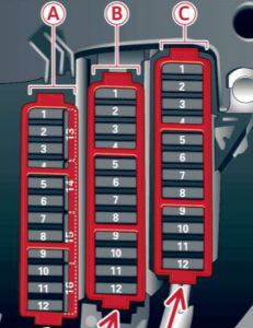
Audi Q5 (2008 – 2017) – fuse box diagram
Year of production: 2005, 2006, 2007, 2008, 2009, 2010, 2011, 2012, 2013, 2014, 2015, 2016, 2017
Location
The fuses are located at the front left and right of the cockpit and behind the trim on the right side of the luggage compartment.
Left cockpit the fuse assignment

Fuse panel A – black |
||
| No. | Equipment | A |
|---|---|---|
| 1 | Dynamic steering | 5 |
| 3 | Homelink | 5 |
| 5 | Climate control | 5 |
| 6 | Right headlight range adjustment | 5 |
| 7 | Left headlight range adjustment | 5 |
| 8 | Vehicle electrical system controls module 1 | 5 |
| 9 | Adaptive cruise control | 5 |
| 10 | Shift gate | 5 |
| 11 | Heater washer flu id nozzles | 5 |
| 12 | Climate control | 5 |
| 13 | Cell phone prep | 5 |
| 14 | Airbag | 5 |
| 15 | Terminal 15 | 25 |
| 16 | Terminal 15 engine | 40 |
Fuse panel B – brown |
||
| No. | Equipment | A |
| 1 | Automatic dimming interiorrearview mirror | 5 |
| 2 | Clutch sensor | 5 |
| 3 | Fuel pump | 25 |
| 5 | Left seat heating | 30 |
| 6 | Electronic Stabilization Program | 10 |
| 7 | Horn | 25 |
| 8 | Left door window regulator motor | 30 |
| 9 | Wiper motor | 30 |
| 10 | Electronic Stabilization Program | 25 |
| 11 | Left doors | 15 |
| 12 | Rain and light sensor | 5 |
Fuse panel C – red |
||
| No. | Equipment | Amps |
| 3 | Lumbar support | 10 |
| 4 | Dynamic steering | 35 |
| 5 | Climatized cupholder | 10 |
| 6 | Vehicle electrical system control module 1 | 35 |
| 7 | Vehicle electrical system control module 1 | 20 |
| 8 | Vehicle electrical system control module 1 | 30 |
| 9 | Panorama sunroof | 20 |
| 10 | Vehicle electrical system control module 1 | 30 |
| 11 | Panorama sunroof shade | 20 |
| 12 | Convenience electronics | 5 |
Right cockpit fuse assignment
Fuse panel A – black |
||
| No. | Equipment | A |
|---|---|---|
| 5 | Steering column switch module | 5 |
| 6 | Electronic Stabilization Program | 5 |
| 7 | Terminal 15 diagnostic connector | 5 |
| 8 | Gateway | 5 |
Fuse panel B – brown |
||
| 1 | CD /DVD player | 5 |
| 2 | Audi drive select switch module | 5 |
| 3 | MMI/Radio | 5/20 |
| 4 | Instrument cluster | 5 |
| 5 | Gateway | 5 |
| 6 | Ignition lock | 5 |
| 7 | Rotary light switch | 5 |
| 8 | Climate control system blower | 40 |
| 9 | Steering column lock | 5 |
| 10 | Climate control | 10 |
| 11 | Terminal 30 diagnostic connector | 10 |
| 12 | Steering column switch module | 5 |
Right luggage compartment fuse assignment
Fuse panel A – black |
||
| No. | Equipment | A |
|---|---|---|
| 1 | Luggage compartment lid control module | 30 |
| 5 | Electromechanical parking brake | 5 |
| 6 | Electronic damping control | 15 |
| 7 | Electromechanical parking brake | 30 |
| 8 | Vehicle electrical system control module 2 | 30 |
| 10 | Vehicle electrical system control module 2 | 30 |
| 11 | Vehicle electrical system control module | 20 |
| 12 | Terminal 30 | 5 |
Fuse panel B – brown |
||
| No. | Equipment | Amps |
| 1 | Luggage compartment lid control module | 30 |
| 2 | Right front seat heating | 15 |
| 3 | DCDC converter path 1 | 40 |
| 4 | DCDC converter path 2 | 40 |
| 7 | Electromechanical parking brake | 30 |
| 9 | Right door control module | 30 |
| 11 | Right door control module | 15 |
Fuse panel C – red |
||
| No. | Equipment | Amps |
| 1 | Rear center console outlet | 15 |
| 2 | Center console front outlet/ climatized cupholder | 15 |
| 3 | Luggage compartment outlet | 15 |
| 4 | Cigarette lighter | 15 |
| 7 | Parking system | 7.5 |
| 8 | Rear wiper | 15 |
| 9 | Electromechanical parking brake switch | 5 |
| 10 | Audi side assist | 5 |
| 12 | Terminal 15 control modules | 5 |
Fuse panel D – black |
||
| No. | Equipment | A |
| 3 | DSP amp lifier, radio | 30 |
| 4 | MMI | 7.5 |
| 5 | Radio/navigat ion/cell phone prep | 5 |
| 6 | Rearview camera | 5 |
| 7 | cell phone prep | 5 |
WARNING: Terminal and harness assignments for individual connectors will vary depending on vehicle equipment level, model, and market.