BMW X5 (E53; 2000 – 2006) – fuse box diagram
Year of production: 2000, 2001, 2002, 2003, 2004, 2005, 2006
Instrument panel fuse box diagram
It is located under the glove compartment.

| № | A | Component |
|---|---|---|
| F1 | 5A | Data bus connection, instrument panel |
| F2 | 5A | Lamps control module |
| F3 | 5A | Heater/air conditioning (AC) (until 02/01) |
| F4 | 5A | Ignition coil relay |
| F5 | 7,5A | Alternator, engine oil level sensor, fuse box/relay plate cooling fan motor |
| F6 | 5A | Interior rearview mirror, parking aid control module(until 02/04), tyre pressure monitor control module |
| F7 | 5A | Ignition coil relay |
| F8 | 5A | Instrument illumination |
| F9 | 5A | Airbag, brake pedal position (BPP)switch, lamps control module |
| F10 | 15A | Horn |
| F11 | 5A | Immobilizer |
| F12 | 5A | Instrument illumination, steering position sensor |
| F13 | 5A | Alarm system, interior rearview mirror |
| F14 | 5A | Multifunction control module 1 |
| F15 | 5A | Tyre pressure monitor control module (until 02/04) |
| F16 | 5A | Ignition switch |
| F17 | 5A | Interior lamps control module |
| F18 | – | – |
| F19 | – | – |
| F20 | 30A | Door function control module, driver |
| F21 | 30A | Electric seats |
| F22 | – | – |
| F23 | – | – |
| F24 | 30A | Door function control module, passenger |
| F25 | 25A | Charging socket, cigarette lighter |
| F26 | 30A | Ignition main circuits relay |
| F27 | 20A | Multifunction control module 1 |
| F28 | 30A | Headlamp washers |
| F29 | 10A | Airbag |
| F30 | – | – |
| F31 | 5A | Engine management |
| F32 | 5A | Ignition main circuits relay, multifunctioncontrolmodule2 |
| F33 | 5A | Cigarette lighter |
| F34 | 7,5A | Heated rear window, heater/air conditioning (AC) |
| F35 | – | – |
| F36 | 5A | Charging socket |
| F37 | 5A | Multifunction control module 2 |
| F33 | – | – |
| F39 | 5A | Clutch pedal position (CPP) switch, immobilizer |
| F40 | 30A | Windscreen wipers |
| F41 | 5A | Rear screen wash/wipe system, multifunction control module 1 |
| F42 | 5A | Interior lamps |
| F43 | 5A | Instrument panel |
| F44 | 5A | Airbag, electric seats |
| F45 | 5A | Instrument panel |
| F46 | 7,5A | Transfer box control module |
| F47 | 25A | Fuel pump (FP) relay |
| F48 | 7,5A | Heater/air conditioning (AC) |
| F49 | – | – |
| F50 | – | – |
| F51 | 10A | Anti-lock brake system (ABS), engine management |
| F52 | 15A | Datalink connector (DLC) (until 09/00) |
| F53 | 25A | Multifunction control module 2 |
| F54 | 15A | Transmission control module(TCM) |
| F55 | 30A | Anti-lock brake system (ABS) |
| F56 | – | – |
| F57 | 15A | Suspension control module |
| F58 | 20A | Sunroof |
| F59 | 20A | Auxiliary heater |
| F60 | 30A | Multifunction control module 1 |
| F61 | 50A | Engine coolant blower motor |
| F62 | 50A | Secondary air injection (AIR) pump relay |
| F63 | 50A | Anti-lock brake system (ABS) |
| F64 | 50A | Heater/air conditioning (AC) |
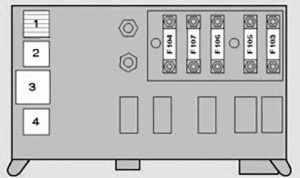
Relay block under the glove compartment
It is located behind the fuse box.

| № | A | Component |
|---|---|---|
| 1 | Fuel lift pump relay – Diesel | |
| 2 | – | |
| 3 | Interior lamps control module | |
| 4 | Horn relay | |
| F103 | – | – |
| F104 | 100A | Glow plugs |
| F105 | 80A | Immobilizer, ignition switch-4,4/4,6 ( until 02/02) |
| F106 | 50A | Ignition switch, lamps control module |
| F107 | 50A | Lamps control module |
Fuse box in the luggage compartment

| № | A | Component |
|---|---|---|
| 1 | Seat heater relay- rear | |
| 2 | Heated rear window relay | |
| 3 | Audio unit relay | |
| 4 | Boot lid/tailgate release relay- lower | |
| 5 | Seat adjustment relay, rear | |
| 6 | Boot lid/tailgate release relay- upper | |
| F72 | 30A | Audio system, navigation system |
| F73 | 7.5A | Ignition coil relay |
| F74 | 10A | Telephone |
| F75 | 5A | Audio system, navigation system |
| F76 | – | – |
| F77 | 30A | Electric seats-rear |
| F78 | 20A | Trailer socket |
| F79 | 7.5A | Suspension control module |
| F80 | 20A | Ignition coil relay |
| F81 | 20A | Rear screen wash/wipe system |
| F82 | – | – |
| F83 | 20A | Charging socket-rear |
| F84 | 7.5A | Boot lid/tailgate lock |
| F85 | 30A | Heated rear window |
| F86 | 5A | Auxiliary heater |
| F87 | 30A | Suspension compressor pump |
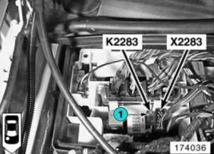
Some relays can also be located under the lining, in the luggage compartment. For example, a compressor pump relay, a pneumatic suspension pump compressor relay.
Fuses and relay in the engine compartment

WARNING: Terminal and harness assignments for individual connectors will vary depending on vehicle equipment level, model, and market.
