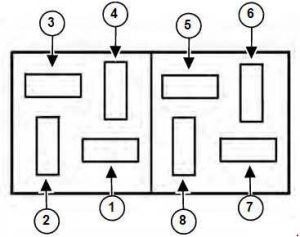
Bobcat 324 (Mini excavator) – fuse box diagram
Year of production:
Fuse box

| Number | Ampers | Protected circuit |
| 1 | 10 | Instrument – Hourmeter, Warning Buzzer and Fuel Gauge Back Light |
| 2 | 20 | Accessory – Accessory Connector, Heater and Horn. |
| 3 | 20 | Start – Key Switch, Unswitched Accessory Connector |
| 4 | 15 | Cab – Cab Power, Lights, Wiper and Dome Light |
| 5 | 15 | Power – Appliance Socket |
| 6 | 15 | Time Power – Stop Timer Module |
| 7 | 15 | Power – Stop Timer Module |
| 8 | — | — |
The excavator has a 12 volt, negative ground electrical system. The electrical system is controlled by fuses and relays located in the right side of the engine compartment (Items 1 and 2). The fuses will protect the electrical system when there is an electrical overload. The reason for the overload must be found and corrected before starting the engine again..
WARNING: Terminal and harness assignments for individual connectors will vary depending on vehicle equipment level, model, and market.