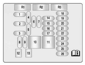
Buick LaCrosse (2013 – 2015) – fuse box diagram
Year of production: 2013, 2014, 2015
Engine Compartment Fuse Block
| J-Case | Usage |
| 6 | Wiper |
| 12 | Starter |
| 21 | Rear power windows |
| 22 | Sunroof |
| 24 | Front power windows |
| 25 | Rear heated seats |
| 26 | Antilock brake system pump |
| 27 | Electric parking brake |
| 28 | Rear window defogger |
| 41 | Brake vacuum pump |
| 42 | Cooling fan K2 |
| 43 | Not Used |
| 44 | Transmission auxiliary oil pump (eAssist) |
| 45 | Cooling fan K1 |
| 59 | AIR pump |
| Mini Fuses | Usage |
| 1 | Transmission control module–battery |
| 2 | Engine control module battery |
| 3 | Air Conditioning Compressor Clutch |
| 5 | Engine control module/Run/Crank |
| 7 | Long range radar/ Front camera |
| 8 | Ignition coils–even (6–cylinder engine)/ Ignition coils–all (4–cylinder engine) |
| 9 | Ignition coils–odd (6–cylinder engine) |
| 10 | Engine control module–switched battery |
| 11 | 6–cylinder Engine: post catalytic converter/O2 sensor/ Heater/Mass air flow sensor/FlexFuel sensor/Secondary air induction solenoid |
| 13 | Crank for transmission control module/Fuel pump power/Chassis control module (eAssist) |
| 14 | Cabin heater coolant pump (eAssist)/ secondary air injector/Secondary air injector with pressure sensor |
| 15 | Motor generator unit coolant pump (eAssist) |
| 16 | Run/Crank for eAssist power inverter module |
| 17 | Not Used |
| 18 | Sunshade module/ Vehicle air purification system/ Ventilated seats |
| 20 | Heated steering wheel (non eAssist) |
| 23 | Variable effort steering (if equipped) or eAssist power inverter module |
| 29 | Heated seat/Left power lumbar |
| 30 | Heated Seat/Right power pack cooling fan (eAssist) |
| 31 | AWD/Electronic suspension control |
| 32 | Body control module 6 |
| 33 | Memory seat–front |
| 34 | Antilock brake system valves |
| 35 | Amplifier |
| 36 | Adaptive forward lighting (AFL) motors–battery |
| 37 | Right high-beam |
| 38 | Left high-beam |
| 46 | Cooling fan relay |
| 47 | Six Cylinder Engine: Pre Catalytic Converter Oxygen Sensor Heater, Canister Purge Solenoid. Four Cylinder Engine: Pre and Post Catalytic Converter Oxygen Sensor Heaters, Canister Purge Solenoid |
| 48 | Fog lamps |
| 49 | Right High Intensity Discharge Headlamp |
| 51 | Horn |
| 52 | Cluster Run/Crank |
| 53 | Run/Crank for: rearview mirror/Rear vision camera/Air quality sensor/Aero shutter motor |
| 54 | Run/Crank for: HVAC/Headlamp switch |
| 55 | Outside rearview mirror/Universal remote system/Front window switches |
| 56 | Windshield washer |
| 60 | Heated mirror |
| 62 | Canister vent |
| 64 | Adaptive forward lighting (AFL) module–battery |
| 65 | Not Used |
| 66 | AIR solenoid (eAssist) |
| 67 | Fuel pump power module/Chassis control module |
| 69 | Regulated voltage control sensor |
| 70 | Parking assist/Side blind zone |
| 71 | Passive entry/ Passive start |
| Mini Relays | Usage |
| 7 | Engine control module |
| 9 | Cooling fan |
| 13 | Cooling fan |
| 15 | Run/Crank |
| 16 | AIR pump |
| 17 | Rear window defogger |
| Micro Relays | Usage |
| 1 | A/C Clutch |
| 2 | Starter |
| 4 | Wiper speed |
| 5 | Wiper control |
| 6 | Cabin heater coolant pump (eAssist)/ Secondary air injector/Secondary air injector with pressure senso |
| 10 | Cooling fan |
| 14 | Headlamp low-beam |
| Ultra Micro Relays | Usage |
| 11 | Transmission auxiliary oil pump (eAssist) |
Instrument Panel Fuse Block
The instrument panel fuse block is in the instrument panel, on the driver side of the vehicle.

| Fuses | Usage |
| 1 | APO 3 |
| 2 | Body control module 7 |
| 3 | Steering wheel controls backlight |
| 4 | Radio/Human machine interface/ Rear auxiliary audio jack/Front auxiliary audio video jack/ Touchpad/Remote media player/Bluray remote media player |
| 5 | OnStar/Universal hands–free phone |
| 6 | Power outlet 1 |
| 7 | Power outlet 2 |
| 8 | Body control module 1 |
| 9 | Body control module 4 |
| 10 | Body control module 8 |
| 11 | Front HVAC/Blower |
| 12 | Passenger seat |
| 13 | Driver seat |
| 14 | Diagnostic link connector |
| 15 | Airbag/Automatic occupant sensing |
| 16 | Trunk |
| 17 | HVAC Controller |
| 18 | Pre-fuse for fuses 4 and 5 |
| 19 | Center stack displays/Head-up display/Right steering wheel control switch/Rear seat infotainment display (eAssist)/ HVAC/Center stack displays |
| 20 | Rear seat entertainment display/Rear seat audio |
| 21 | Instrument cluster |
| 22 | Discrete logic ignition switch |
| 23 | Body control module 3 |
| 24 | Body control module 2 |
| 25 | Rear HVAC/Blower |
| 26 | AC DC inverter |
| Relays | Usage |
| R1 | Trunk relay |
| R2 | — |
| R3 | Power outlet relay |
WARNING: Terminal and harness assignments for individual connectors will vary depending on vehicle equipment level, model, and market.