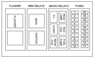
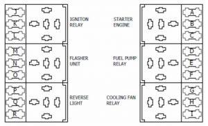
Caterham Seven – fuse box diagram
Year of production:
Location
The fuse box is located under the dashboard on the vertical face of the engine bulkhead.
K6A Suzuki
 Caterham Seven – fuse box diagram – K6A Suzuki
| № |
A |
Component |
| Fuses |
| 1 |
5 |
EMS Wake-Up |
| 2 |
7,5 |
EMS Ignition Supplies (non-critical) |
| 3 |
10 |
Brake/Reverse Lamps |
| 4 |
7,5 |
Ignition Services |
| 5 |
7,5 |
Heater |
| 6 |
10 |
Demist |
| 7 |
10 |
Washers & Wipers |
| 8 |
10 |
Power socket |
| 9 |
7,5 |
Horns |
| 10 |
15 |
Headlamps |
| 11 |
15 |
Headlamp Flash |
| 12 |
15 |
EMS Ignition Supplies (critical) |
| 13 |
10 |
Flasher Unit |
| 14 |
5 |
Diagnostic Connector |
| 15 |
7,5 |
Side Lamps & Rear Fog Light |
| 16 |
7,5 |
Immobiliser |
| 17 |
10 |
EMS ECU Power |
| 18 |
— |
Spare |
| 19 |
15 |
Fuel Pump |
| 20 |
15 |
Cooling Fan |
Fuses and relays – Sigma
| № |
A |
Component |
| Relays |
| 1 |
Ignition |
| 2 |
Lights |
| 3 |
Indicator |
| 4 |
Hazard |
| 5 |
Starter |
| 6 |
Fuel Pump |
| 7 |
Cooling Fan |
| Fuses |
| A |
7,5 |
Brake Lights |
| B |
5 |
Reverse Light |
| C |
7,5 |
Instruments |
| D |
7,5 |
Heater |
| E |
10 |
Heated Screen |
| F |
5 |
Rear Fog Light |
| G |
7,5 |
R/H Side/Tail Light |
| H |
5 |
L/H Side/Tail Light |
| I |
15 |
Main Beam |
| J |
15 |
Dip Beam |
| K |
15 |
Wipe/Wash |
| L |
7,5 |
Horn |
| M |
10 |
Flasher Unit |
| N |
15 |
Fuel Pump |
| O |
10 |
Power Socket |
| P |
15 |
Ignition Supply Engine |
| Q |
15 |
Ignition Supply Engine |
| R |
15 |
Ignition Supply Engine |
| S |
15 |
Ignition Supply Engine |
| T |
15 |
Main Feed Engine |
| U |
7,5 |
Acc Cluster engine |
Fuses and relays – Duratec
 Caterham Seven – fuse box diagram – Duratec
Duratec (excl. EU4 175 & 237)
| № |
A |
Component |
| Relays |
| 1 |
Ignition |
| 2 |
Flasher |
| 3 |
Reverse |
| 4 |
Starter |
| 5 |
Fuel pump |
| 6 |
Cooling Fan |
| Fuses |
| A |
15 |
Ignition Supply |
| B |
15 |
Ignition Supply – Engine |
| C |
20* |
Cooling Fan |
| D |
15 |
Fuel Pump |
| E |
10 |
Brake / Reverse Lights |
| F |
7,5 |
Instruments |
| G |
7,5 |
Heater |
| H |
10 |
Heated Screen |
| I |
10 |
Wash / Wipe |
| J |
10 |
Power Socket |
| K |
7,5 |
Horn |
| L |
15 |
Flasher Unit – Fog / Dipped Beam |
| M |
5 |
Switch LED’s |
| N |
7,5 |
Side Lights |
| O |
10 |
Flasher Unit / D.C.M |
| P |
15 |
P.C.M Main Supply |
| Q |
15 |
Main Beam |
| R |
5 |
Keyless Immobilizer |
| * * 620R uses 30A |
Fuses and relays – Duratec EU4 175 / 237
| № |
A |
Component |
| Relays |
| 1 |
Starter |
| 2 |
Ignition |
| 3 |
Reverse |
| 4 |
Flasher |
| Fuses |
| 1 |
15 |
ECU/lambda IGN |
| 2 |
15 |
Engine IGN |
| 3 |
10 |
Brake/Reverse |
| 4 |
7,5 |
Instruments/relay drives/immobiliser |
| 5 |
7,5 |
Heater |
| 6 |
10 |
Demist |
| 7 |
10 |
Wipe/Wash |
| 8 |
10 |
Power socket |
| 9 |
7,5 |
Horn |
| 10 |
15 |
Dip Beam |
| 11 |
5 |
Switch LED/Relay drives |
| 12 |
7,5 |
Side Lights |
| 13 |
10 |
Flasher Unit/DCM |
| 14 |
15 |
ECU main supply |
| 15 |
15 |
Main Beam |
| 16 |
7,5 |
Immobiliser |
| 17 |
5 |
ACC Pedal |
| 18 |
15 |
Engine IGN |
| 19 |
20 |
ECU main supply |
| 20 |
20 |
ECU main supply |
WARNING: Terminal and harness assignments for individual connectors will vary depending on vehicle equipment level, model, and market.


