Chery Arrizo 7 (M16; 2013 – 2018) – fuse and relay box diagram
Year of production: 2013, 2014, 2015, 2016, 2017, 2018
Passenger Compartment Fuse Box
Fuse Box Location
The Instrument panel fuse box is located on the lower left side of instrument panel.
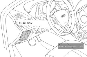
Fuse Box Diagram
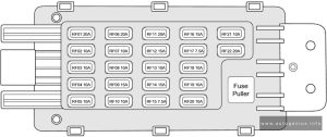
Assignment of the fuses in the instrument panel
| № | Description |
|---|---|
| RF01 | Reserve |
| RF02 | A/C System / Audio System / Shift Mechanism (CVT) / IGN2 Relay Coil (w/o PEPS) |
| RF03 | SRS Control Module |
| RF04 | ESP (ABS) / Steering Angle Sensor |
| RF05 | Instrument Cluster |
| RF06 | Reserve |
| RF07 | PEPS (w/ PEPS) / ECM/TCU (CVT) |
| RF08 | A/C Integrated Switch / BCM / EPS |
| RF09 | Cigarette Lighter |
| RF10 | A/C Integrated Switch / Audio System / BCM |
| RF11 | Reserve |
| RF12 | Reserve |
| RF13 | Power Outside Rear View Mirror Switch / Blower and ACC Relay Coil (w/o PEPS) |
| RF14 | Reserve |
| RF15 | Sliding Roof Switch / Diagnostic Interface |
| RF16 | Reserve |
| RF17 | Reserve |
| RF18 | A/C Control Panel and A/C High/Low Pressure Switch |
| RF19 | Audio System |
| RF20 | Instrument Cluster |
| RF21 | Spare |
| RF22 | Spare |
Engine compartment fuse box
Fuse Box Location
The fuse box is located on the left side of engine compartment and the rear side of left headlight.
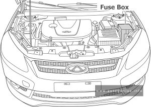
Fuse Box Diagram
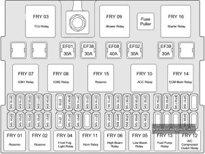
Assignment of the fuses in the engine compartment
| № | Description |
|---|---|
| EF01 | Ignition Switch (w/o PEPS) |
| EF02 | Driver Seat Power Adjustment |
| EF03 | Immobilizer Control Module (w/o PEPS) / Brake Switch |
| EF04 | Ignition Switch (w/o PEPS) |
| EF05 | PEPS (w/ PEPS) / TCU / TCU Relay Coil (CVT) |
| EF06 | ESP (ABS) |
| EF07 | IP Fuse Box (B+) |
| EF08 | ESP (ABS) |
| EF09 | Reserve |
| EF10 | Reserve |
| EF11 | TCU / Gearbox / Gear Shift Mechanism (CVT) |
| EF12 | Front Fog Light |
| EF13 | Headlight Leveling Switch |
| EF14 | Right Headlight Low Beam / Right Headlight Adjustment Motor |
| EF15 | Left Headlight Low Beam / Left Headlight Adjustment Motor |
| EF16 | Right Headlight High Beam |
| EF17 | Left Headlight High Beam |
| EF18 | PEPS (w/ PEPS) |
| EF19 | IP Fuse Box (ON) |
| EF20 | Sliding Roof Motor |
| EF21 | Brake Switch / Sliding Roof Motor |
| EF22 | Back-up Light |
| EF23 | Reversing Radar Control Module |
| EF24 | Blower |
| EF25 | Backup Power Supply |
| EF26 | IP Fuse Box (ACC) |
| EF27 | Horn |
| EF28 | A/C Compressor Clutch Switch |
| EF29 | Fuel Pump Motor |
| EF30 | ECM |
| EF31 | Ignition Coil |
| EF32 | Upstream Oxygen Sensor |
| EF33 | Injector |
| EF34 | Variable Intake Valve / Canister Solenoid Valve / Variable Camshaft Timing (Intake/Exhaust) |
| EF35 | Cooling Fan Control Module |
| EF36 | Downstream Oxygen Sensor |
| EF37 | ECM |
| EF38 | Reserve |
| EF39 | Starter Control |
Power fuses
The power fuses are located at side of engine compartment fuse and relay box.
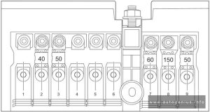
| № | Description |
|---|---|
| 1 | – |
| 2 | Trunk Fuse and Relay Box |
| 3 | BCM |
| 4 | – |
| 5 | – |
| 6 | – |
| 7 | EPS |
| 8 | Alternator |
| 9 | Cooling Fan |
Luggage compartment fuse box
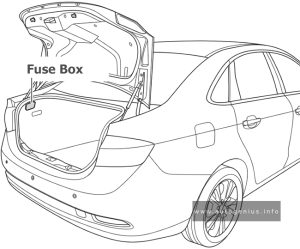
Fuse Box Location
Trunk fuse and relay box is located in the trunk, next to the trunk light.
Fuse Box Diagram
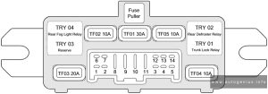
Assignment of the fuses in the engine compartment
| № | Description |
|---|---|
| TF01 | Rear Defroster |
| TF02 | Rear Fog Light |
| TF03 | Reserve |
| TF04 | Trunk Lock |
| TF05 | Antenna Amplifier |
WARNING: Terminal and harness assignments for individual connectors will vary depending on vehicle equipment level, model, and market.
