Chevrolet Aveo (2012) – fuse box diagram
Year of production: 2012
Engine compartment
The fuse box is located in engine compartment.
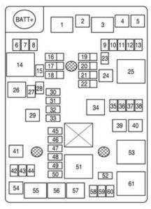
Petrol

| Number | Circuit |
| 1 | Front wiper speed relay |
| 2 | ABS pump |
| 3 | Front wiper control relay |
| 4 | Front wiper |
| 5 | Blower |
| 6 | ABS valve |
| 7 | Sunroof |
| 8 | — |
| 9 | Rear wiper |
| 10 | RVC |
| 11 | ABS oil |
| 12 | AOS/ROS |
| 13 | OSRVM |
| 14 | Rear defog relay |
| 15 | Rear window defog |
| 16 | Spare fuse |
| 17 | Spare fuse |
| 18 | Spare fuse |
| 19 | Spare fuse |
| 20 | Spare fuse |
| 21 | Spare fuse |
| 22 | Spare fuse |
| 23 | — |
| 24 | RUN/CRANK IEC |
| 25 | RUN/CRANC relay |
| 26 | — |
| 27 | — |
| 28 | OSRVM HTD |
| 29 | — |
| 30 | Front seat heated |
| 31 | — |
| 32 | Flux fuel |
| 33 | Washer |
| 34 | Fuel pump relay |
| 35 | Fuel pump |
| 36 | ECM/TCM |
| 37 | — |
| 38 | — |
| 39 | Cool fan K5 |
| 40 | Cool fan K4 |
| 41 | EVP |
| 42 | ECM |
| 43 | Ac clutch |
| 44 | TCM |
| 45 | ECM_1 |
| 46 | Coil |
| 47 | ECM_4 |
| 48 | ECM_3 |
| 49 | ECM_2 |
| 50 | Injector |
| 51 | P/T relay |
| 52 | Horn |
| 53 | Cool fan K3 relay |
| 54 | Start |
| 55 | Start relay |
| 56 | AC clutch relay |
| 57 | High beam relay |
| 58 | Front fog |
| 59 | High beam LH |
| 60 | High beam RH |
| 61 | Cool fan K1 relay |
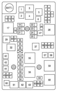
Diesel

| Number | Circuit |
| 1 | Front wiper speed relay |
| 2 | ABS pump |
| 3 | Front wiper control relay |
| 4 | Front wiper |
| 5 | Variable water pump power relay |
| 6 | Blower |
| 7 | Variable water pump power |
| 8 | OSRVM |
| 9 | AOS/ROS |
| 10 | ABS oil |
| 11 | RVC |
| 12 | Rear wiper |
| 13 | — |
| 14 | ABS valve |
| 15 | Sunroof |
| 16 | — |
| 17 | Rear defog relay |
| 18 | Rear window defog |
| 19 | Spare fuse |
| 20 | Spare fuse |
| 21 | Spare fuse |
| 22 | Spare fuse |
| 23 | Spare fuse |
| 24 | Spare fuse |
| 25 | Spare fuse |
| 26 | — |
| 27 | RUN/CRANK IEC |
| 28 | RUN/CRANK relay |
| 29 | Aux water pump power relay |
| 30 | Aux water pump power |
| 31 | OSRVM HTD |
| 32 | Fuel filter heater relay |
| 33 | Front seat heated |
| 34 | — |
| 35 | Washer |
| 37 | Fuel pump relay |
| 38 | Fuel pump |
| 39 | ECM/TCM |
| 40 | FSCM 2 |
| 41 | DC/DC Converter |
| 42 | Fuel filter heater |
| 43 | REC |
| 44 | Glow plug |
| 45 | ECM |
| 46 | AC clutch |
| 47 | TCM |
| 49 | ECM_1 |
| 50 | COIL |
| 51 | ECM_4 |
| 52 | ECM_3 |
| 53 | ECM_2 |
| 54 | Injector |
| 55 | Cool fan K2 relay |
| 56 | P/T relay |
| 57 | Cool fan K5 |
| 58 | Cool fan K4 |
| 59 | Cool fan K3 relay |
| 60 | Start |
| 61 | Start relay |
| 62 | AC clutch relay |
| 63 | High beam relay |
| 64 | Horn |
| 65 | Front fog |
| 66 | High beam LH |
| 67 | High beam RH |
| 68 | Cool fan K1 relay |
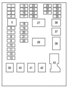
Instrument panel fuse box
Interior fuse box is located on the underside of the driver’s side instrument panel.

| Number | Circuit |
| 1 | DLIS |
| 2 | DLC |
| 3 | Airbag |
| 4 | Tail gate |
| 5 | Spare fuse |
| 6 | Body control module |
| 7 | Body control module |
| 8 | Body control module |
| 9 | Body control module |
| 10 | Body control module |
| 11 | Body control module |
| 12 | Body control module |
| 13 | Body control module |
| 14 | IPC |
| 15 | ONSTAR |
| 16 | Ultra parking assist |
| 17 | Driver information center |
| 18 | Audio |
| 19 | Trailer |
| 20 | VLBS |
| 21 | CHEVYSTAR |
| 22 | Heating, ventilation, air conditioning |
| 23 | HDLP ALC |
| 24 | Clutch |
| 25 | IPC-AOS |
| 26 | Airbag RUN/CRANK |
| 27 | Run relay |
| 28 | Tail gate relay |
| 29 | Trailer RUN/CRANK |
| 30 | Clock spring |
| 31 | Heating, ventilation, air conditioning |
| 32 | Spare fuse |
| 33 | Sunroof |
| 34 | Cigarette lighter |
| 35 | Spare fuse |
| 36 | Rear power window |
| 37 | Front power window |
| 38 | RAP/ACCY |
| 39 | DCDC CONV |
| 40 | Driver power window |
| 41 | PTC2 |
| 42 | PTC1 |
| 43 | Battery connector |
WARNING: Terminal and harness assignments for individual connectors will vary depending on vehicle equipment level, model, and market.
