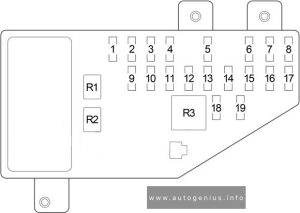
Chrysler Cirrus (1995 – 2000) – fuse and relay box diagram
Year of production: 1995, 1996, 1997, 1998, 1999, 2000
The Chrysler Cirrus is a mid-size sedan that was produced by Chrysler from 1995 to 2000. Part of Chrysler’s “Cloud Car” series, the Cirrus shared its platform with the Dodge Stratus and Plymouth Breeze, with each model offering slightly different features and trim levels. The Cirrus was designed to offer a balance of style, performance, and comfort in the competitive mid-size sedan market of the 1990s.
The Chrysler Cirrus was a stylish, comfortable, and reasonably well-equipped sedan for its time. It offered a good blend of power (particularly with the V6 engine), a smooth ride, and modern design cues. While it is no longer in production, the Cirrus remains a memorable part of Chrysler’s history in the mid-size sedan segment.
Passenger Compartment Fuse Box
Fuse Box Location
Fuse Box Diagram

Assignment of fuses in the instrument panel
| No. |
A |
Protected Component |
| 1 | 30 | Blower Motor |
| 2 | 20 | Convertible: Right Headlamp (High Beam), Daytime Running Lamp Module |
| 10 | Right Headlamp (High Beam), Daytime Running Lamp Module | |
| 3 | 20 | Convertible: Left Headlamp (High Beam) |
| 10 | Left Headlamp (High Beam) | |
| 4 | 15 | Back-Up Lamp (Back-Up Lamp Switch (M/T), Transmission Range Sensor (A/T)), Power Top Relay (Convertible), Daytime Running Lamp Module, Power Door Lock Switch, Power Mirror Switch, Automatic Day/Night Mirror, Steering Proportional Steering Module |
| 5 | 10 | Dome Lamp, Data Link Connector, Power Antenna, Overhead Map Lamp, Trunk Lamp, Traveler, Body Control Module, Radio, Glove Box Lamp, Visor/Vanity Lamp, Universal Garage Door Opener, Automatic Day/Night Mirror, Illuminated Entry Relay, Courtesy Lamp, Power Door Lock Switch, Door Arm/Disarm Switch, Key-In Halo Lanp, Sunroof Control Module |
| 6 | 10 | Heated Mirror, A/C Heater Control |
| 7 | 20 | ’98-’00: Instrument Cluster, Headlamp Switch |
| 15 | ’95-’97: Headlamp Switch | |
| 8 | 20 | Cigar Lighter/Power Outlet, Horn Relay |
| 9 | 15 | Body Control Module |
| 10 | 20 | Rear Fog Lamp Switch, Daytime Running Lamp Module |
| 11 | 10 | Body Control Module, Instrument Cluster, Autostick Switch, Transmission Control Module |
| 12 | 10 | Left Headlamp (Low Beam), Daytime Running Lamp Module |
| 13 | 20 | Right Headlamp (Low Beam), Front Fog Lamp Switch |
| 14 | 10 | Radio |
| 15 | 10 | Combination Flasher, Seat Belt Control Module (Convertible), Intermittent Wiper Relay, Wiper (High/Low) Relay, Rear Window Defogger Relay |
| 16 | 10 | Airbag Control Module |
| 17 | 10 | Airbag Control Module |
| Circuit Breaker | ||
| 18 | 20 | Power Seat Switch, Decklid Release Relay |
| 19 | 20 | Power Window, Master Power Window Switch, Window Timer Module, Sunroof Control module |
| Relay | ||
| R1 | Headlamp Delay | |
| R2 | Horn | |
| R3 | Rear Window Defogger | |
Engine Compartment Fuse Box
Fuse Box Location
Fuse Box Diagram
Assignment of fuses in the engine compartment
| No. |
A |
Protected Component |
| 1 | 10 | Oxygen Sensor Downstream |
| 2 | 20 | ABS |
| 3 | 20 | Transmission Control Module, Transmission Control Relay |
| 4 | 20 | Stop Lamp Switch, Fuse (Passenger Compartment): “5” |
| 5 | 20 | Automatic Shut Down Relay (Fuel Injectors, Ignition Coil Pack (2.0L and 2.4L), Noise Suppressor (2.0L and 2.4L), Generator, Oxygen Sensor Upstream, Distributor (2.5L) EGR Solenoid, Fuse: “1”), Powertrain Control Module |
| 6 | 20 | Combination Flasher, Sentry Key Immobilizer Module |
| 7 | 10 | Ignition Switch (Fuse (Passenger Compartment): “11”) |
| 8 | 20 | Starter Relay, Fuel Pump Relay, Ignition Switch (Body Control Module, Clutch Interlock Switch (M/T), Transmission Control Module (EATX), Fuse (Passenger Compartment): “14”, “15”, “17”, Fuse (Engine Compartment): “9”, “10”) |
| 9 | 10 | Air Conditioner Compressor Clutch Relay, Radiator Fan (High Speed) Relay, Radiator Fan (Low Speed) Relay, Fuel Pump Module, Instrument Cluster, Sentry Key Immobilizer Module, Brake Shift Interlock Solenoid |
| 10 | 10 | Fuel Pump Relay, Powertrain Control Module, ABS |
| 11 | 20 | Convertible: Seat Belt Control Module |
| 12 | 40 | Rear Window Defogger Relay |
| 13 | 40 | ABS |
| 14 | 40 | Fuse (Passenger Compartment): “7”, “8” |
| 15 | 40 | Headlamp Switch, Headlamp Delay Relay (Body Control Module, Headlamp Switch, Fuse (Passenger Compartment): “12”, “13”), Fuse (Passenger Compartment): “9”, “10””18″ |
| 16 | 40 | Ignition Switch (Fuse (Passenger Compartment): “1”, “4”, “16”, “19”) |
| 17 | 40 | Convertible: Power Top Up/Down Relays |
| 18 | 40 | Intermittent Wiper Relay (Wiper (High/Low) Relay) |
| 19 | 40 | Air Conditioner Compressor Clutch Relay, Radiator Fan (High Speed) Relay, Radiator Fan (Low Speed) Relay |
| Relay | ||
| R1 | Radiator Fan (High Speed) | |
| R2 | Automatic Shut Down | |
| R3 | Radiator Fan (Low Speed) | |
| R4 | Starter | |
| R5 | – | |
| R6 | Air Conditioner Compressor Clutch | |
| R7 | Convertible: Power Tow | |
| R8 | Intermittent Wiper | |
| R9 | Wiper (High/Low) | |
| R10 | Fuel Pump | |
| R11 | Transmission Control | |
| R12 | – | |
WARNING: Terminal and harness assignments for individual connectors will vary depending on vehicle equipment level, model, and market.