Chrysler Crossfire (2004 – 2008) – fuse box diagram
Year of production: 2004, 2005, 2006, 2007, 2008
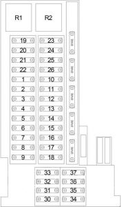
Engine Compartment Fuse Box (No.1)

| No. |
A |
Protected Component |
| 1 | 5 | Stop Lamp Switch, Garage Door Opener (Europe), Universal Garage Door Opener, Tire Pressure Monitor, Heated Seat Module |
| 2 | 5 | Occupant Restraint Controller, Passenger Seat Occupant Simulator, Left/Right Side Impact Sensor |
| 3 | 5 | Instrument Cluster, Airbag Off Indicator Lamp |
| 4 | 7.5 | Power Mirror |
| 5 | 15 | Radio |
| 25 | Convertible: Power Top Control Module | |
| 6 | 5 | Power Mirror Switch |
| 40 | Convertible: Power Top Hydraulic Assembly | |
| 7 | 5 | Body Control Module, Automatic Day/Night Mirror, Intrusion Sensor |
| 8 | 15 | Radio |
| 9 | 10 | Dome Lamp, Cargo Lamp, Siren, Anti-Theft Tow Sensor, Intrusion Sensor, Body Control Module, Universal Garage Door Opener, Tire Pressure Monitor |
| 10 | 5 | Speed Control Switch |
| 11 | 15 | Ignition Coils, Noise Suppressor |
| 12 | 10 | Heated Washer Nozzles |
| 13 | 10 | SRT: Charge Air Cooler Circulation Pump |
| 14 | 10 | Data Link Connector, Steering Angle Sensor |
| 15 | 5 | Coolant Circulation Pump, Coolant Circulation Valve |
| 16 | 10 | Body Control Module |
| 17 | 40 | ABS |
| 18 | 40 | ABS |
| 19 | 40 | Body Control Module |
| 20 | 40 | Body Control Module |
| 21 | 30 | RHD: Driver Power Seat |
| 30 | LHD: Passenger Power Seat | |
| 22 | 30 | RHD: Passenger Power Seat |
| 30 | LHD: Driver Power Seat | |
| 23 | 15 | Power Amplifier |
| 24 | 30 | Heated Seat Module |
| 25 | 20 | Central Locking Pump/Security System Module |
| 26 | 20 | Central Locking Pump/Security System Module |
| 30 | 15 | Convertible: Radio |
| 31 | 15 | Cigar Lighter, Glove Box Lamp |
| 32 | 15 | Multi-Function Switch |
| 33 | 5 | A/C Heater Control Module |
| 34 | 30 | Convertible: Blower Motor |
| 35 | 15 | Instrument Cluster, Remote Keyless Entry Relay, Console Switch Group, Key-In Ignition Switch, Sentry Key Remote Entry Module, A/C Heater Control Module |
| 36 | 30 | Blower Motor |
| 5 | Convertible: Power Mirror Switch | |
| 37 | 5 | A/C Heater Control Module, Recirculated Air Switchover Valve, Sentry Key Remote Entry Module, Instrument Cluster, Illumination Control Module, Ash Receiver Lamp, Power Window Switch, Power Top Switch, Console Switch Group, Radio |
| Relay | ||
| R1 | Stop Lamp | |
| R2 | Remote Keyless Entry | |
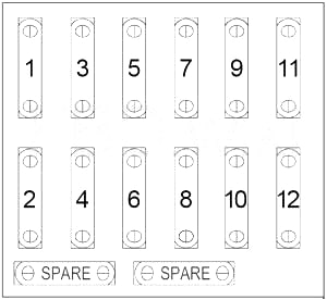
Passenger Compartment Fuse Box

| No. |
A |
Protected Component |
| 1 | – | – |
| 2 | 15 | Stop Lamp Switch, ABS, Stop Lamp Relay |
| 3 | 7.5 | Right High Beam, High Beam Indicator Lamp |
| 4 | 15 | Back-Up Lamp, Turn Signal Lamp, Automatic Day/Night Mirror, Radio |
| 5 | 7.5 | Left High Beam |
| 6 | 15 | Right Low Beam |
| 7 | 7.5 | Front Right Parking Light, Right Side Marker, Right Taillamp |
| 8 | 15 | Left Low Beam |
| 9 | 15 | Front Fog Lamp |
| 10 | 7.5 | Front Left Parking Light, Left Side Marker, Left Taillamp |
| 11 | 7.5 | License Lamp, Instrument Cluster, Ash Receiver |
| 12 | 7.5 | Rear Fog Lamp |
Engine Compartment Fuse Box (No.2)

| No. |
A |
Protected Component |
| 1 | 15 | Traction System Relay |
| 2 | 15 | Oxygen Sensors, Air Pump Relay, EVAP Purge Solenoid, Charcoal Canister Shutoff Valve, Air Pump Switchover Solenoid, EGR Solenoid (except SRT), Supercharger Clutch (SRT), Short Runner Valve Solenoid (except SRT) |
| 3 | 15 | Powertrain Control Module, Fuel Injectors, Camshaft Position Sensor, Fuel Pump Relay |
| 4 | 40 | Air Pump Relay |
| 5 | 15 | Fuel Pump Relay |
| 6 | 15 | Horn Relay |
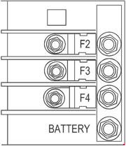
Fusible Link Block

| No. |
A |
Protected Component |
| F2 | 50 | Radiator Fan Control Module |
| F3 | 50 | ABS, Pulse Module |
| F4 | 200 | Main |
WARNING: Terminal and harness assignments for individual connectors will vary depending on vehicle equipment level, model, and market.
