Citroen Relay II – Citroen Jumper II (2006 – 2010) – fuse box diagram
Year of production: 2006,2007, 2008, 2009, 2010
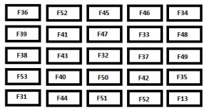
Fuse box in instrument panel (driver side)

Remove the bolts and tilt the box to access the fuses.
| Fuses | Ampere rating [A] | Allocation |
| 12 | 7,5 | Right-hand dipped headlamp |
| 13 | 7,5 | Left-hand dipped headlamp – Headlamp height adjuster |
| 31 | 7,5 | Relay supply |
| 32 | 10 | Minibus interior lighting – Hazard warning lights |
| 33 | 15 | Rear 12 V socket |
| 34 | — | Not used |
| 35 | 7,5 | Reversing lights – Water in diesel sensor |
| 36 | 20 | Door locking/unlocking unit |
| 37 | 10 | Brake lights switch – Third brake light – Instrument panel |
| 38 | 10 | Interior relays |
| 39 | 10 | Audio equipment – Diagnostics socket – Alarm siren – Programmable additional heating controls |
| 40 | 15 | De-icing: rear screen (left-hand side), mirror (passenger side) |
| 41 | 15 | De-icing: rear screen (right-hand side), mirror (driver’s side) |
| 42 | 7,5 | ABS control unit and sensor – ESP sensor – Brake lights switch |
| 43 | 30 | Windscreen wiper motor |
| 44 | 20 | Lighter – Front 12 V socket |
| 45 | 7,5 | Electric window and mirror switches (driver’s side) – Passenger electric window |
| 46 | — | Not used |
| 47 | 20 | Driver’s electric window motor |
| 48 | 20 | Passenger electric window motor |
| 49 | 7,5 | Rain/brightness sensor – Audio equipment – Driver’s electric window motor – Alarm – Instrument panel controls |
| 50 | 7,5 | Air bags and pre-tensioners unit |
| 51 | 7,5 | Chronotachograph – Cruise control – Air conditioning controls |
| 52 | 7,5 | Passenger compartment relays |
| 53 | 7,5 | Instrument panel – Rear fog lamps |
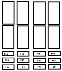
Driver’s pillar fuses

| Fuses | Ampere rating [A] | Allocation |
| 54 | — | Not used |
| 55 | 15 | Heated seats |
| 56 | 15 | Rear 12 V socket – Lighter |
| 57 | 10 | Ventilation/heating motor under the driver’s seat |
| 58 | 10 | Direction indicators |
| 59 | — | Not used |
| 60 | — | Not used |
| 61 | — | Not used |
| 62 | — | Not used |
| 63 | 10 | Programmable additional heating switch |
| 64 | — | Not used |
| 65 | 30 | Rear blower |
Fuse box in engine compartment
| Fuse | Ampere rating [A] | Allocation |
| 1 | 10 | ABS/ESP pump supply |
| 2 | 50 | Diesel pre-heat unit |
| 3 | 30 | Ignition switch |
| 4 | 20 | Programmable additional heating burner |
| 5 | 20 | Programmable additional heating controls relay |
| 6 | 40 | Fan assembly (high speed) |
| 60 | ||
| 7 | 40 | Fan assembly (low speed) |
| 50 | ||
| 8 | 40 | Air conditioning |
| 9 | 20 | Windscreen wash pump |
| 10 | 15 | Horn |
| 11 | 15 | Diesel pre-heat unit and relay |
| 14 | 7,5 | Right-hand main beam headlamp |
| 15 | 7,5 | Left-hand main beam headlamp |
| 16 | 7,5 | Engine control unit |
| 17 | 10 | Engine control unit |
| 18 | 7,5 | Engine control unit |
| 19 | 7,5 | Air conditioning compressor |
| 20 | 30 | Headlamp wash pump |
| 21 | 15 | Fuel pump supply |
| 22 | 20 | Engine control unit |
| 23 | 10 | ABS/ESP solenoid valves supply |
| 24 | — | Not used |
| 30 | 15 | Front fog lamps |
WARNING: Terminal and harness assignments for individual connectors will vary depending on vehicle equipment level, model, and market.
