Dodge Durango (2001 – 2003) – fuse and relay box diagram
Year of production: 2001, 2002, 2003
Passenger compartment
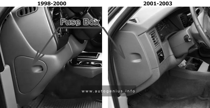
Fuse box location
The fuse panel is located behind the cover on the driver’s side of dash panel.
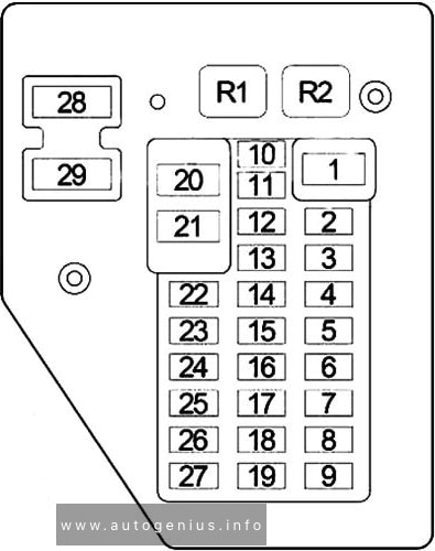
Fuse box diagram
Assignment of the fuses in the engine compartment
| № | Amps | Description |
|---|---|---|
| 1 | 15A | Sentry Key Immobilizer, Instrument Cluster, Radio, Center Console Lamp, Overhead Console, Front/Rear Dome Lamp, Glove Box Lamp/Switch, Data Link Connector, Driver Door Module, Right/Left Visor/Vanity Mirror & Liftgate Lamp |
| 2 | 20A | Horn Relay & Clockspring |
| 3 | – | – |
| 4 | 20A | Central Timer Module, Headlamp Switch, Left/Right Tail Lamp Assembly, Left/Right Front Park/Turn Signal Lamps, Left/Right Front Side Marker Lamp & License Plate Lamp |
| 5 | 20A | Front Wiper Relay, Front Wiper Motor & Central Timer Module |
| 6 | – | – |
| 7 | – | – |
| 8 | 10A | Transmission Control Module & Instrument Cluster |
| 9 | 5A | Rear A/C Heater Control, Overhead Console, Transfer Case Selector Switch, Shift Bezel Lamp, Radio, Cigar Lighter, A/C Heater Control & Instrument Cluster |
| 10 | 10A | Powertrain Control Module, Fuel Pump Relay, Radiator Fan Relay & Sentry Key Immobilizer |
| 11 | 10A | A/C Compressor, Proportional Purge Solenoid, Automatic Day/Night Mirror, Overhead Console, Central Timer Module & Transfer Case Selector Switch |
| 12 | 10A | Engine Starter Motor Relay & Transmission Control Module |
| 13 | 15A | Amplifier |
| 14 | 10A | Instrument Cluster |
| 15 | 10A | Driver/Passenger Power Mirror |
| 16 | – | – |
| 17 | 15A | Cigar Lighter |
| 18 | 10A | Radio |
| 19 | 10A | Combination Flasher |
| 20 | 10A | Airbag Control Module |
| 21 | 10A | Airbag Control Module |
| 22 | 20A | Heated Seat Module & Passenger/Driver Heated Seat Module |
| 23 | – | – |
| 24 | 15A | Rear Window Defogger Relay & Rear Blower Motor Relay |
| 25 | 10A | A/C Heater Control |
| 26 | 15A | Transmission Solenoid, Transmission Range Sensor & Passenger Door Power Lock Switch |
| 27 | 10A | Controller Anti-Lock Brake |
| 28 | 25A CB | Driver Door Module (Power Window) |
| 29 | – | – |
| R1 | Horn Relay | |
| R2 | Park Lamp Relay |
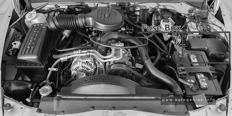
Engine Compartment
Fuse box location
Fuse box diagram
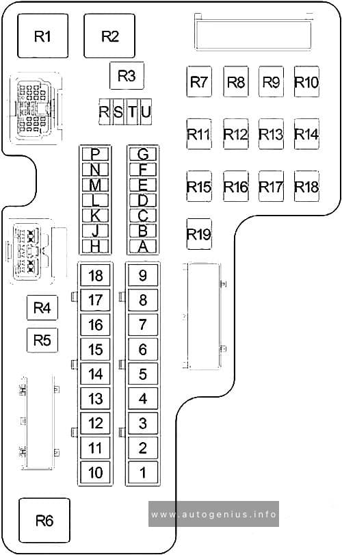
Assignment of the fuses in the engine compartment
| № | Amps | Description |
|---|---|---|
| A | 20A | Transfer Case Control Module |
| B | 10A | A/C Compressor Clutch Relay |
| C | 20A | Trailer Tow Connector |
| D | 20A | Junction Block & Front/Center/Rear Power Outlet |
| E | 20A | Ignition Switch |
| F | 20A | Transmission Control Relay |
| G | – | – |
| H | 20A | Fog Lamp Relay |
| J | 20A | Rear Wiper Relay |
| K | 25A | Rear Blower Motor Relay |
| L | – | – |
| M | – | – |
| N | – | – |
| P | – | – |
| R | – | – |
| S | – | – |
| T | 10A | Left/Right Front Park/Turn Signal Lamps, Left/Right Side Marker Lamp & License Lamp |
| U | 20A | Oxygen Sensors, Fuel Injectors Coil On Plugs, Powertrain Control Module & Ignition Coil |
| 1 | 20A/30A | Combination Flasher |
| 2 | 20A | Powertrain Control Module, Automatic Shut Down Relay & Fuel Pump Module/Relay |
| 3 | 20A | Central Timer Module |
| 4 | 40A | Rear Window Defogger Relay |
| 5 | 20A | Brake Lamp Switch |
| 6 | 30A | Electric Brake |
| 7 | 40A | Junction Block |
| 8 | 40A | Controller Anti-Lock Brake |
| 9 | 50A | Ignition Switch |
| 10 | 40A | Ignition Switch |
| 11 | 30A | Automatic Shut Down Relay |
| 12 | 20A | Central Timer Module |
| 13 | 40A | Ignition Switch |
| 14 | 50A | Driver/Passenger Power Seat Switch |
| 15 | 50A | Radiator Fan Relay & Driver/Passenger Power Relay |
| 16 | 50A | Engine Starter Motor Relay |
| 17 | 50A | Ignition Switch |
| R1 | Radiator Fan Relay | |
| R2 | Automatic Shut Down (ASD) Relay | |
| R3 | – | |
| R4 | Rear Blower Motor Relay | |
| R5 | – | |
| R6 | EBL Relay | |
| R7 | Fuel Pump Relay | |
| R8 | – | |
| R9 | Air Conditioner Compressor Clutch Relay | |
| R10 | Fog Lamp Relay | |
| R11 | – | |
| R12 | Oxygen Sensor Relay | |
| R13 | – | |
| R14 | Transmission Control Relay | |
| R15 | – | |
| R16 | – | |
| R17 | Starter Relay | |
| R18 | Front Wiper Relay | |
| R19 | Rear Wiper Relay |
WARNING: Terminal and harness assignments for individual connectors will vary depending on vehicle equipment level, model, and market.