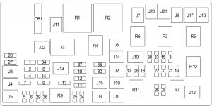
Dodge Ram 2500 (2011 – 2013) – fuse box diagram
Year of production: 2011, 2012, 2013
Fuse box diagram

| No. |
A |
Protected Component |
| 1 | 15 | Stop Lamp Switch |
| 2 | 20 | – |
| 3 | 30 | except for 6.7L: Drive Train Control Module |
| 4 | – | – |
| 5 | 25 | 115V AC Inverter |
| 6 | 20 | Cigar Lighter (Instrument Panel) or Power Outlet (Front Console), Rain Sensor |
| 7 | 20 | Rear Power Outlet or Power Outlet (Center Seat) |
| 8 | 20 | Front Heated Seat, Steering Wheel |
| 9 | 20 | Rear Heated Seats |
| 10 | 15 | Compass Module, Hands-Free Module, Video Screen Module, Satellite Video Module, Universal Garage Door Opener Module, Vanity Lamp |
| 11 | 10 | A/C Heater Control, Underhood Lamp |
| 12 | 30 | Radio, Radio Amplifier |
| 13 | 20 | Cluster, Multi-Function Switch, Steering Column Module, Siren, Tire Pressure Monitoring System, Wireless Control Module |
| 14 | 20 | Back-Up Camera |
| 15 | 20 | Cluster, Multi-Function Switch, Steering Angle Sensor, Trailer Tow Module, Transfer Case Selector Switch, Inside Rearview Mirror, Fuel Heated Relay (6.7L), O2 Sensor Module, Drive Train Control Module (except 3.7L), Power Seat Module, Audio Telematics, Daytime Running Lights Relay |
| 16 | 10 | Occupant Restraint Controller Module (Airbag) |
| 17 | – | – |
| 18 | 15 | Center Stop Lamp |
| 19 | 25 | Automatic Shutdown (No.1, No.2) |
| 20 | 15 | Cluster, Lower Bank Switch, Upper Bank Switch, Steering Control Module Instrument |
| 21 | 20 | Automatic Shutdown (No.3) |
| 22 | 10 | Horn (Right) |
| 23 | 10 | Horn (Left) |
| 24 | – | – |
| 25 | 20 | Gasoline: Fuel Pump Motor |
| 20 | Diesel: Lift Pump | |
| 26 | 10 | Driver Window/Door Lock Switch |
| 27 | 10 | Ignition Switch |
| 28 | 15 | except for 6.7L: Powertrain Control Module (PCM) |
| 29 | 10 | Tire Pressure Monitoring System |
| 30 | 15 | Diagnostic Connector |
| 31 | 20 | Back-Up Lamp Switch |
| 32 | 10 | Occupant Restraint Controller Module (Airbag) |
| 33 | 10 | Powertrain Control Module (PCM) |
| 34 | 10 | A/C Heater Control, Infrared Sensor, Park Assist Module, Radiator Fan (High) Relay (except 6.7L), Compass Module |
| 35 | 15 | Left Front & Rear Parklamps |
| 36 | 20 | Power Outlet (Front Console) or Cigar Lighter (Instrument Panel) |
| 37 | 10 | Stop Lamp Switch, ABS, Dynamics Sensor |
| 38 | 25 | Door Lock Relay, Driver Door Unlock Relay, Passenger Door Unlock Relay |
| J1 | 40 | Trailer Tow |
| J2 | 30 | Brake Provision Module |
| J3 | 30 | Diesel: Powertrain Control Module (PCM) |
| J4 | 25 | Driver Door Module |
| J5 | 25 | Passenger Door Module |
| J6 | 40 | ABS |
| J7 | 30 | ABS |
| J8 | 40 | Circuit Breaker (CB1 – Power Seat) |
| J9 | 30 | – |
| J10 | 30 | Sway Bar Module |
| J11 | 30 | Transfer Case Module |
| J12 | 30 | Rear Window Defogger |
| J13 | 60 | Fuse: “10”, “11”, “12”, “13” |
| J14 | 20 | Trailer Tow Lamps/Park Lamps |
| J15 | 40 | Front Blower |
| J16 | – | – |
| J17 | 40 | Starter |
| J18 | 20 | Powertrain Control Module Transmission Range |
| J19 | 60 | Radiator Fan (Low) Relay, Radiator Fan (High) Relay |
| J20 | 30 | Wiper On/Off Relay |
| J21 | 20 | Washer Control |
| J22 | 25 | Sunroof Module |
| Circuit Breaker | ||
| CB1 | 25 | Power Seat |
| Relay | ||
| R1 | Ignition (Run/Acc) | |
| R2 | Ignition (Run) | |
| R3 | Starter | |
| R4 | Run-Start | |
| R5 | Transmission Control Module (TCM) | |
| R6 | Park Lamp | |
| R7 | EBL | |
| R8 | – | |
| R9 | Blower Motor | |
| R10 | Automatic Shutdown | |
| R11 | Radiator Fan (Low) | |
WARNING: Terminal and harness assignments for individual connectors will vary depending on vehicle equipment level, model, and market.