
Dodge Ram 4500 Chassis Cab (2012) – fuse box diagram
Year of production: 2012
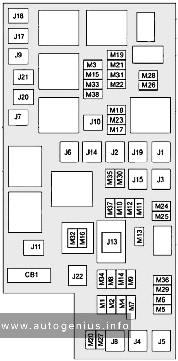
Engine Compartment
Fuse Box Location
The Totally Integrated Power Module is located in the engine compartment near the battery. This center contains cartridge fuses and mini fuses. A description of each fuse and component may be stamped on the inside cover, otherwise the cavity number of each fuse is stamped on the inside cover.

Fuse box diagram
| № | Cartridge Fuse | Mini Fuse | Description |
|---|---|---|---|
| J01 | 40A Green | Trailer Tow | |
| J02 | 30A Pink | Electric Brake | |
| J03 | 30A Pink | Diesel Powertrain Control Module – If Equipped | |
| J04 | 25A Natural | Driver Door Node | |
| J05 | 25A Natural | Passenger Door Node | |
| J06 | 40A Green | Antilock Brakes Pump / Stability Control System | |
| J07 | 30A Pink | Antilock Brakes Valve / Stability Control System | |
| J08 | 40A Green | Power Seat | |
| J10 | 30A Pink | Sway Bar Module – If Equipped | |
| J11 | 30A Pink | Transfer Case Module | |
| J12 | 30A Pink | Rear Defroster | |
| J13 | 60A Yellow | Main Ignition Off Draw (IOD) Fuse | |
| J14 | 20A Blue | Trailer Tow Lamps / Park Lamps | |
| J15 | 40A Green | Front Blower | |
| J17 | 40A Green | Starter Motor Solenoid | |
| J18 | 20A Blue | Powertrain Control Module Transmission Range | |
| J19 | 60A Yellow | Rad Fan Motor HI / Rad Fan Motor Low | |
| J20 | 30A Pink | Front Wiper Ground / Low/High | |
| J21 | 20A Blue | Washer Control | |
| J22 | 25A Natural | Sunroof Module | |
| M1 | 15A Blue | Stop Switch Lamp | |
| M5 | 25A Natural | 115V AC Inverter | |
| M6 | 20A Yellow | Power Outlet (Instrument Panel or Front Console) / Rain Snsr | |
| M7 | 20A Yellow | Power Outlet (Rear Console or Center Seat) | |
| M8 | 20A Yellow | Front Heated Seat & Steering Wheel | |
| M9 | 20A Yellow | Rear Heated Seats | |
| M10 | 15A Blue | Hands Free Module / Vanity Lamp / Universal Garage Door Opener Module | |
| M11 | 10A Red | Climate Control System | |
| M12 | 30A Green | Radio / Amplifier | |
| M13 | 20A Yellow | Main #2 Instrument Cluster / Wireless Control Module / ITM / Siren / Multifunction Switch (Steering Column Module) | |
| M14 | 20A Yellow | Back Up Camera (Domestic Only) | |
| M15 | 20A Yellow | Power Seat Module(s) /Audio Telematics / Daytime Running Lights Relay / Instrument Cluster/Transfer Case Module | |
| M16 | 10A Red | Airbag Module | |
| M18 | 15A Blue | Center Stop Lamp | |
| M19 | 25A Natural | Automatic Shutdown 1 and 2 | |
| M20 | 15A Blue | Instrument Cluster Interior Lighting / Sw Steering Wheel / Sw Bank | |
| M21 | 20A Yellow | Automatic Shutdown 3 | |
| M22 | 10A Red | Horns (Low/High) – Right | |
| M23 | 10A Red | Horns (Low/High) – Left | |
| M25 | 20A Yellow | Fuel Pump Motor / Diesel Lift Pump – If Equipped | |
| M26 | 10A Red | Driver’s Door Switch | |
| M27 | 10A Red | Ignition Switch | |
| M28 | 15A Blue | Powertrain Control Module | |
| M29 | 10A Red | Tire Pressure Monitor | |
| M30 | 15A Blue | J1962 Diag Connector | |
| M31 | 20A Yellow | Back-Up Lamps | |
| M32 | 10A Red | Airbag Module | |
| M33 | 10A Red | Powertrain Control Module | |
| M34 | 10A Red | Park Assist Module / Climate Control System Module / IR Sensor / Compass Module | |
| M35 | 15A Blue | Left Front & Rear Parklamps | |
| M36 | 20A Yellow | Power Outlet (Instrument Panel or Center Console) | |
| M37 | 10A Red | Antilock Brakes / Stability Control System Module / Stoplamp Switch | |
| M38 | 25A Natural | All Door Lock&Unlock |
WARNING: Terminal and harness assignments for individual connectors will vary depending on vehicle equipment level, model, and market.