Dodge Sprinter (2003 – 2006) – fuse box diagram
Year of production: 2003, 2004, 2005, 2006
Fuse Box No.1
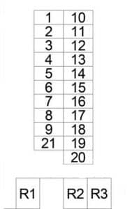
| No. |
A |
Circuit Protected |
| 1 | 10 | Headlamp Switch |
| 2 | 10 | Headlamp Right (High Beam) |
| 3 | 10 | Headlamp Left (High Beam), Instrument Cluster |
| 4 | 10 | Shifter Assembly |
| 5 | 10 | Stop Lamp Switch, Data Link Connector |
| 6 | 20 | Multi-Function Switch (Wiper/Turn Signal/Engine Start Control Module) |
| 7 | 15 | Optional Equipment Relay, Lamp Relay – Right (Trailer Tow Connector, Tail Lamp, Headlamp), Sentry Key Remote Entry Module, Horn (VTSS), Rear Window Defogger Switch, Circulation Pump Relay, Transmission Control Relay, Horn Relay |
| 8 | 20 | Cigar Lighter, Radio, Auxiliary Heater Switch, Turn Signal/Anti-Theft Alarm Relay – Left/Right, Courtesy Lamp, Interior Lamp, Dome Lamp |
| 9 | 15 | Multi-Function Switch (Hazard Warning Switch) |
| 10 | 10 | Map/Reading Lamp Switch, Interior Light Switch, Radio, A/C Fan Switch, Automatic Temperature Control Module, Headlamp Adjust Switch, Panic Alarm Switch, A/C Switch – Roof, Temperature Switch, Shifter Assembly, TCS Switch (ASR), Master Door Lock Switch, Towing/Intrusion Sensor On/Off Switch, Ash Receiver Lamp, Fog Lamp Switch, Rear Window Defogger Switch, Locker Switch No.1, Cigar Lighter Lamp |
| 11 | 10 | Left Lamp Relay (Headlamp, Tail Lamp) |
| 12 | 10 | Headlamp Right (Low Beam), Daytime Running Lamp Relay – Right |
| 13 | 10 | Headlamp Left (Low Beam), Daytime Running Lamp Relay – Left |
| 14 | 15 | Fog Lamp Relay |
| 15 | 10 | Radio, Radio/Cellular Antenna, Central Timer Module, |
| 16 | 15 | Engine Control Module |
| 17 | 15 | Engine Control Module, EGR Valve, Crankcase Heater |
| 18 | 15 | Run-Start Relay, Engine Control Module, Instrument Cluster, Airbag Control Module |
| 19 | 15 | – |
| 20 | 15 | Circulation Pump Relay, Automatic Temperature Control Module |
| 21 | 30 | Blower Motor |
| Relay | ||
| R1 | Engine Control | |
| R2 | Wiper On/Off | |
| R3 | Turn Signal | |
Fuse Box No.2

| No. |
A |
Circuit Protected |
| 1 | 10 | Daytime Running Lamp Relay (Instrument Cluster, Headlamp Left, Headlamp Right, License Plate Lamp, Marker Lamp) |
| 2 | 10 | Transmission Control Relay |
| 3 | 15 | Instrument Panel Socket |
| 4 | 7.5 | Left Lamp Relay, Right Lamp Relay |
| 5 | 25 | Central Timer Module |
| 6 | 7.5 | Data Link Connector, Instrument Cluster |
| 7 | 25 | Power Window Switch – Driver |
| 8 | 10 | Power Mirror Switch, Driver/Passenger Power Mirror Motor |
| 9 | 15 | A/C Switch – Roof, Rear Window Defogger Module, Central Timer Module, D+ Relay No.2, Daytime Running Lamp Relay, Right Lamp Relay, Auxiliary Battery Relay |
| 10 | 7.5 | Daytime Running Lamp Relay (Right Side) |
| 11 | 7.5 | Daytime Running Lamp Relay (Left Side) |
| 12 | 25 | Body Plug Connector |
| 13 | 15 | Run-Start Relay |
| 14 | 10 | D+ Relay 2 |
| 15 | 25 | Power Window Switch – Master, Power Window Switch – Passenger |
| 16 | – | |
| 17 | – | |
| 18 | – |
Fuse Box No.3
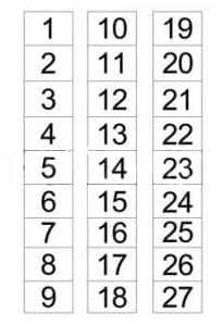
| No. |
A |
Circuit Protected |
| 1 | 7.5 | Auxiliary Heater Timer |
| 2 | 7.5 | Security System Module, Siren, Intrusion Sensor No.1/No.2/No.3 |
| 3 | 25 | Auxiliary Heater Relay |
| 4 | 25 | Cabin Heater Assembly |
| 5 | 7.5 | Fog Lamp Switch |
| 6 | 25 | Trailer Tow Control Module, Trailer Tow Connector |
| 7 | 10 | Circulation Pump Diode, Cabin Heater Assembly, Auxiliary Heater Relay |
| 8 | 10 | Fan Stage 1 Relay |
| 9 | 30 | CTEL Connector |
| 10 | 15 | Security System Module |
| 11 | 25 | Warm Air Auxiliary Heater Assembly |
| 12 | 15 | Locker Switch No.1/No.2 |
| 13 | 7.5 | CTEL Connector |
| 14 | 7.5 | Security System Module |
| 15 | 15 | Driver/Passenger Heated Seat Switch |
| 16 | – | |
| 17 | – | |
| 18 | 15 | Map/Reading Lamp Switch, Interior Light Switch, Time Delay Relay, |
| 19 | 15 | |
| 20 | 15 | A/C Fan Switch |
| 21 | – | |
| 22 | – | |
| 23 | – | |
| 24 | – | |
| 25 | – | |
| 26 | – | |
| 27 | – |
Fuse Box No.4
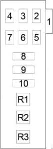
| No. |
A |
Circuit Protected |
| 1 | 30 | A/C Auxiliary Fan Relay |
| 2 | – | – |
| 3 | – | – |
| 4 | – | – |
| 5 | 10 | Sentry Key Remote Entry Module, Turn Signal/Anti-Theft Alarm Relay – Left, Turn Signal/Anti-Theft Alarm Relay – Right |
| 6 | 7.5 | ABS |
| 7 | 25 | ABS |
| 8 | 40 | A/C Control Module – Roof |
| 9 | 40 | ABS |
| 10 | 30 | Rear Window Defogger Module, Rear Window Defogger Relay – Left, Rear Window Defogger Relay – Right |
| Relay |
||
| R1 | – | |
| R2 | Starter | |
| R3 | – | |
Relay Box
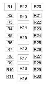
| No. |
Relay |
| R1 | – |
| R2 | Turn Signal/Anti-Theft Alarm – Left |
| R3 | Turn Signal/Anti-Theft Alarm – Right |
| R4 | Lamp – Left |
| R5 | Lamp – Right |
| R6 | Transmission Control |
| R7 | D+ No.1 |
| R8 | Daytime Running Light |
| R9 | Fog Lamp |
| R10 | Daytime Running Lamp – Left |
| R11 | Daytime Running Lamp – Right |
| R12 | Circulation Pump |
| R13 | Run-Start |
| R14 | Time Delay |
| R15 | Auxiliary Heater |
| R16 | Optional Equipment |
| R17 | Fan Stage 1 |
| R18 | A/C Auxiliary Fan |
| R19 | – |
| R20 | – |
| R21 | Auxiliary Battery |
| R22 | D+ No.2 |
| R23 | Rear Window Defogger – Left |
| R24 | – |
| R25 | Rear Window Defogger – Right |
| R26 | – |
| R27 | – |
| R28 | – |
| R29 | – |
| R30 | – |
Fusible Link Block
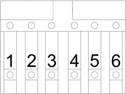
| No. |
A |
Circuit Protected |
| 1 | 200 | Generator |
| 2 | 70 | Optional Equipment Relay (Fuse Box No,2: “6”, “7”, “8”, “15”; Fuse Box No.3: “7”, “12”, “13”, “14”, “15”, “20”; Fuse Box No.4: “6”) |
| 3 | 125 | D+ Relay No.1 (Fuse Box No,2: “9”, “10”, “11”), Fuse Box No,2: “1”, “2”, “3”, “4”, “5”, “6”, “12”, “13”, “14”; Fuse Box No,3: “1”, “3”, “4”, “5”, “6”, “8”, “9”, “11”, “18”, Fuse Box No.4: “1”, “5”, “6”, “7”, “8”, “9”, “10” |
| 4 | 80 | – |
| 5 | 125 | Glow Plug Control Module |
| 6 | 100 | Ignition Switch, Engine Control Relay, Starter Relay, Fuse Box No.1: “6”, “8”, “9”, “17”, “19”, “20”, “21”; Fuse Box No,3: “2”, “10” |
WARNING: Terminal and harness assignments for individual connectors will vary depending on vehicle equipment level, model, and market.
