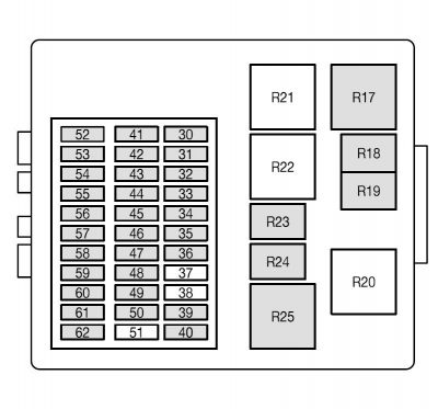
Ford Focus (1999 – 2004) – fuse box diagram
Year of production: 1999, 2000, 2001, 2002, 2003, 2004
Passenger compartment fuse box.
Ford Focus MK1 – fuse box – passenger junction
| Fuse | Ampere rating (A) | Circuits protected |
| 30 | 10 | Light switch |
| 31 | 15 | Radio |
| 32 | 15 | Turn signal hazar flasher |
| 33 | 20 | Horn, power seat |
| 34 | 20 | Power sunroof |
| 35 | 7,5 | Interior lamps, power mirrors |
| 36 | 7,5 | Electronic modulee, instrument cluster |
| 37 | — | Not used |
| 38 | — | Not used |
| 39 | 15 | Rear power point |
| 40 | 10 | Back-up lamps (automatic transmission) |
| 41 | 7,5 | Radio (accessory) |
| 42 | 15 | Stop lamps |
| 43 | 15 | Rear wiper |
| 44 | 20 | Fog lamps |
| 45 | 7,5 | Recirculated air, air conditioning |
| 46 | 7,5 | ABS |
| 47 | 15 | Cigar lighter, front power point |
| 48 | 10 | Data link connector |
| 49 | 25 | Rear defrost |
| 50 | 7,5 | Heated mirrors |
| 51 | — | Not used |
| 52 | 15 | Heated front seats |
| 53 | 10 | Back-up lamps (manual transmission) |
| 54 | 25 | Rear power windows |
| 55 | 25 | Front power windows |
| 56 | 20 | Front wipers |
| 57 | 7,5 | Side lights (right) |
| 58 | 7,5 | Side lights (left) |
| 59 | 10 | Light switch |
| 60 | 7,5 | Air bag module |
| 61 | 7,5 | Electronic modules, instrument cluster |
| 62 | 7,5 | License plate lamp |
| 63 | 20 | Power locks (GEM) (on back side of fuse panel) |
Relays in the passenger compartment fuse panel.
| Relay | Description |
| R17 | Starter |
| R18 | Rear intermitten wipper |
| R19 | Front intermitten wiper |
| R20 | Not used |
| R21 | Not used |
| R22 | Not used |
| R23 | Horn |
| R24 | Battery saver |
| R25 | Rear defrost, heated mirrors |
Engine compartment fuse box.
| Fuse | Ampere rating (A) | Circuits protected |
| 1 | 40 | Main power supply to electrical system |
| 2 | 30 | Engine cooling fan (A/C) 2nd fuse |
| 3 | — | Not used |
| 4 | — | Not used |
| 5 | — | Not used |
| 6 | 50 | Engine cooling fan (A/C) 1st fuse |
| 7 | 40 | Main power supply to electrical system |
| 8 | 30 | Ignition switch, starter |
| 9 | 20 | Engine management |
| 10 | 10 | Battery voltage sensor, diagnostic plug |
| 11 | 30 | ABS |
| 12 | 15 | Fuel pump |
| 13 | — | Not used |
| 14 | — | Not used |
| 15 | 10 | AC clutch solenoid |
| 16 | 10 | Low beam (left side) |
| 17 | 10 | Low beam (right side) |
| 18 | 10 | Heated oxygen sensors |
| 19 | 10 | Low beam (DRL) |
| 20 | 10 | Engine management |
| 21 | 20 | ABS |
| 22 | 20 | Low beam (DRL) |
| 23 | — | Not used |
| 24 | 30 | Powered subwoofer |
| 25 | — | Not used |
| 26 | 10 | High beam (left side) |
| 27 | 10 | High beam (right side) |
| 28 | — | Not used |
| 29 | — | Not used |
| 64 | 10 | Heater blower motor |
| 65 | — | Not used |
Relays in engine compartment fuse box.
| Relay | Circuits switched |
| R1 | Ignition |
| R2 | Not used |
| R3 | Not used |
| R4 | A/C diode |
| R5 | High beams |
| R6 | Low beams |
| R7 | Fuel pump |
| R8 | Engine management |
| R9 | Not used |
| R10 | Not used |
| R11 | Air conditioning |
| R12 | Daytime running lights |
| R13 | Fog lamps |
| R14 | Stop lamp inhibit relay (Advance Trac only) |
| R15 | Engine cooling fan level 2 (A/C) |
| R16 | Engine cooling fan level 1 |
WARNING: Terminal and harness assignments for individual connectors will vary depending on vehicle equipment level, model, and market.

