Ford Ka+ (2014 – 2018) – fuse box diagram
Year of production: 2014, 2015, 2016, 2017, 2018
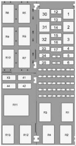
Engine Compartment Fuse Box
 Ford Ka+ – fuse box diagram – engine compartment
| Fuse |
Ampere rating [A] |
Protected components |
| 1 |
40 |
Blower motor |
| 2 |
— |
— |
| 3 |
— |
— |
| 4 |
30 |
Vehicles four and five doors without heated seat, Vehicle five doors with heated seat |
| 40 |
Vehicle four doors with heated seat |
| 5 |
30 |
Starter relay |
| 6 |
— |
— |
| 7 |
— |
— |
| 8 |
5 |
Power control module relay coil, Fuel pump relay coil, Ignition relay coil |
| 9 |
10 |
AC compressor |
| 10 |
— |
— |
| 11 |
— |
— |
| 12 |
— |
— |
| 13 |
— |
— |
| 14 |
— |
— |
| 15 |
— |
— |
| 16 |
— |
— |
| 17 |
20 |
Cigar Lighter |
| 18 |
10 |
Horn |
| 19 |
7,5 |
Heated Mirrors |
| 20 |
20 |
Powertrain control module |
| 21 |
20 |
HEGO sensor, CMS sensor, Purge valve, Variable camshaft timing |
| 22 |
5 |
A/C relay coil. Cooling fan relay coil |
| 23 |
15 |
Ignition coil |
| 24 |
— |
— |
| 25 |
5 |
Wiper relay coil |
| 26 |
5 |
Heated backlite relay coil |
| 27 |
10 |
Anti-lock brake system module, Headlamp leveller |
| 28 |
10 |
Powertrain control module |
| 29 |
— |
— |
| 30 |
— |
— |
| 31 |
40 |
Anti-lock brake system |
| 32 |
— |
— |
| 33 |
30 |
Trailer tow |
| 34 |
20 |
Heated seats |
| 35 |
30 |
Cooling Fan |
| 36 |
— |
Not used |
| 37 |
20 |
Fuel pump, Fuel injectors |
| 38 |
20 |
Electronic stability control module |
| 39 |
10 |
Brake switch |
| 40 |
20 |
Horn relays |
| 41 |
20 |
Front wiper motor |
| 42 |
15 |
Rear wiper motor |
| 43 |
15 |
Horn |
| 44 |
10 |
Daytime running light |
| Relay |
circuits switched |
| R1 |
Powertrain control module and loads |
| R2 |
Wiper |
| R3 |
Ignition loads |
| R4 |
Daytime running light |
| R5 |
Starter motor |
| R6 |
AC compressor |
| R7 |
Heated backlite |
| R8 |
Heated seats |
| R9 |
Horn (Body control module) |
| R10 |
Cooling fan |
| R11 |
— |
| R12 |
Blower motor |
| R13 |
Fuel pump |
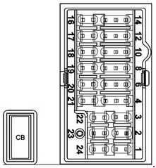
Passenger Compartment Fuse Box
 Ford Ka+ – fuse box diagram – passenger compartment
| Fuse |
Ampere rating [A] |
Protected components |
| 1 |
10 |
Audio unit (without SYNC) |
| 2 |
30 |
— |
| 3 |
20 |
— |
| 4 |
7,5 |
Power windows logic (one touch up/down). Power mirrors |
| 6 |
10 |
Climate control module. SYNC module. Multi function display. Integrated control panel. GPS module. USB charger(without SYNC). |
| 8 |
7,5 |
Instrument cluster. Datalink. Gateway module (with SYNC). |
| 10 |
5 |
Climate control module (without A/C). In-car temperature sensor (with EATC). Electric power assist steering. |
| 12 |
10 |
Airbag control module, Passenger Airbag desactivation switch, Windshield washer pump |
| 14 |
— |
— |
| 16 |
30 |
Body control module ignition relay |
| 17 |
20 |
Radio supply battery |
| 18 |
10 |
Datalink. Gateway module (with SYNC). |
| 19 |
10 |
Ignition switch |
| 20 |
— |
— |
| 21 |
10 |
— |
| 22 |
10 |
Rear parking aid module |
| 23 |
20 |
Power door locks relay |
| 24 |
25 |
— |
| CB01 |
30 |
Circuit Breaker: Power windows |
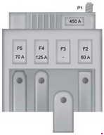
Battery Fuse Box
 Ford Ka+ – fuse box diagram – battery fuse box
| Fuse |
Ampere rating [A] |
Protected components |
| 1 |
450 |
Starter motor. Alternator. |
| 2 |
60 |
Electrical power assisted steering. |
| 3 |
— |
Engine junction box |
| 4 |
125 |
Body control module |
| 5 |
70 |
— |
WARNING: Terminal and harness assignments for individual connectors will vary depending on vehicle equipment level, model, and market.


