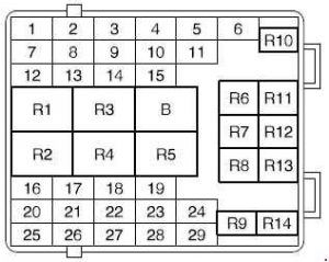
Ford Scorpio (1994 – 1998) – fuse box diagram
Year of production: 1994, 1995, 1996, 1997, 1998
Fuses in the Central Junction Box

| № |
A |
Circuits protected |
| 1 | 15 | Front fog lights, heated exterior mirrors |
| 2 | 5 | Parking light LHD, licence plate light |
| 3 | 10 | Exterior light switch |
| 4 | 10 | Dipped beam right-hand side, headlamp levelling |
| 5 | 10 | Dipped beam left-hand side |
| 6 | 30 | Electrically adjustable seats |
| 7 | 25 | Wiper motors, washer pumps |
| 8 | 5 | Radio |
| 9 | 15 | Horn |
| 10 | 10 | Main beam left-hand side |
| 11 | 10 | Main beam right-hand side |
| 12 | 5 | Parking light RHD |
| 13 | 20 | Ignition lock |
| 14 | 15 | Tail lights, direction indicators, brake lights |
| 15 | 7.5 | Rear fog lights |
| 16 | 7.5 | Electronics |
| 17 | 7.5 | Electronics |
| 18 | 10 | Dim/dipped light RHD |
| 19 | 20 | Headlamp washer |
| 20 | 20 | Heated rear window |
| 21 | 10 | Heated exterior mirrors |
| 22 | 20 | Door locking modules |
| 23 | 5 | Instrument panel light |
| 24 | 15 | Interior lights, audio systems |
| 25 | 30 | Power window |
| 26 | 30 | Power window front |
| 27 | 10 | Air bag, ABS |
| 28 | 30 | Power sunroof, power rear windows |
| 29 | 25 | Heater blower motor |
| R1 | Rear window wiper | |
| R2 | Intermittent wiping (windscreen) | |
| R3 | Dipped beam | |
| R4 | Heated rear window | |
| R5 | Heated rear window | |
| R6 | Main beam | |
| R7 | Dim/dip light (GB) | |
| R8 | Not used | |
| R9 | Fog light | |
| R10 | Horn | |
| R11 | Start inhibitor (automatic transmission) | |
| R12 | Rear door locking | |
| R13 | Bridge | |
| R14 | Daytime running lights (S, N, DK, SF) | |
| Power interruption power windows or electrically adjustable seats Overloading can cause a temporary interruption of the operation of the power windows or the electrically adjustable seats. In case of permanent interruption check the corresponding fuse. |
||
Fuses in the Battery Junction Box
| № |
A |
Circuits protected |
| 30 | 20 | Self-levelling suspension |
| 31 | 10 | EEC V PCM |
| 32 | – | Not used |
| 33 | 20 | Ignition timing |
| 34 | 15 | Engine management system |
| 35 | 30 | Air conditioning compressor |
| 36 | 10 | Power saver (battery) |
| 37 | 20 | Engine management system |
| 38 | 30 | Heated windscreen right-hand side |
| 39 | 30 | Cooling fan (1/1+2) |
| 40 | 20 | HO2S |
| 41 | 30 | Heated windscreen left-hand side |
| 42 | 15 | Fuel pump |
| 43 | 20 | Cigar lighter, electrically heated seats |
| 44 | 30 | Cooling fan (2) |
| 45 | 10 | Hazard flasher |
| 46 | 30 | ABS module |
| 47 | 30 | ABS module |
| I | 80 | Power supply central junction box |
| II | 60 | Power supply central junction box |
| III | 60 | Power supply central junction box |
| IV | 50 | Diesel glow plug |
| R16 | Power saver (battery) | |
| R17 | Fuel injection pump | |
| R18 | Heated windscreen | |
| R19 | Engine management system | |
| R20 | Self-levelling suspension | |
| R21 | Ignition lock | |
| R22 | Bridge | |
| R23 | Bridge | |
| R24 | Air conditioning | |
| R25 | Not used |
Auxiliary Relays and their Location
| № |
Circuits protected |
Location |
| R26 | Heated seats | Centre console |
| R27 | Power sunroof | Sunroof |
| R28 | Heater blower motor | Retainer behind the glove compartment |
| R29 | Direction indicators | Adjacent to the steering column |
| R30 | ‘‘Trip’’ Switch (windows) | Driver’s door |
| R31 | Headlamp washer | Retainer behind the glove compartment |
| R32 | Diesel glow plug | Engine compartment |
| R33 | Rear window wiper interval | Adjacent to the steering column |
| R34 | Engine cooling fan | Engine compartment |
| R35 | Front fog lights (NL,S) | Underneath the instrument panel |
| R36 | Not used | – |
| R37 | Speed control system | Retainer behind the glove compartment |
| R38 | Air compressor | Retainer behind the glove compartment |
WARNING: Terminal and harness assignments for individual connectors will vary depending on vehicle equipment level, model, and market.