
Genesis GV80 (2021 – 2023) US Version – fuse box diagram
Year of production: 2021, 2022, 2023
Passenger Compartment Fuse Box
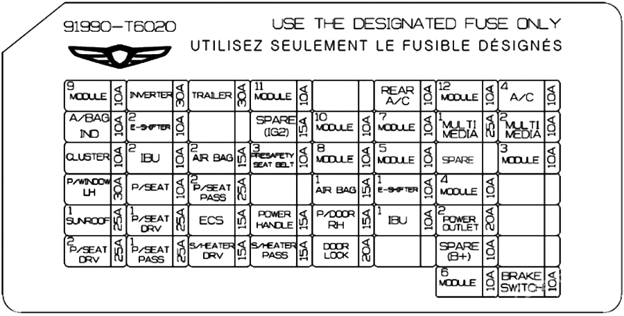
| Fuse Name | Amps | Circuit Protected |
|---|---|---|
| MODULE 9 | 10A | Overhead Console Lamp, AMP, Driver Power Seat Module, Low DC-DC Converter (AMP), 2ND Seat LH/RH Module, Passenger Power Seat Module, Electro Chromic Mirror, 2ND Air Ventilation Seat LH/RH Control Module, 2ND Seat LH/ RH Warmer Control Module, Front A/C Controller, Smart Phone Wireless Charger, Rear A/C Control Panel, Data Link Connector, Low DC-DC Converter, A/V & Navigation Head Unit, Front A/C Control Module |
| INVERTER | 30A | AC Inverter |
| TRAILER | 30A | Trailer Controller |
| MODULE 11 | 10A | Head Lamp LH/RH, Multifunction Switch, AC Inverter, ADAS Unit (Parking),AC Inverter Outlet, Rear Junction Block (Rear Wiper Relay) |
| REAR A/C | 10A | Rear A/C Control Panel, Rear Blower Motor |
| MODULE 12 | 10A | IAU, IBU |
| A/C 4 | 10A | E/R SUB Junction Block (Blower Relay), Incar Temperature Sensor, Front A/C Control Module, Rear A/C Control Panel, Front A/C Controller |
| A/BAG IND | 10A | Instrument Cluster, Overhead Console Lamp |
| E-SHIFTER 2 | 10A | Electronic ATM Shift Lever Dial |
| SPARE (IG2) | 15A | Not Used |
| MODULE 10 | 10A | ICU Junction Block (ESU) |
| MODULE 7 | 10A | Driver Door Module, IBU, Multifunction Switch, IAU, Stop Lamp Switch |
| MULTI MEDIA 1 | 25A | Low DC-DC Converter (with ISG), A/V & Navigation Head Unit (without ISG) |
| MULTI MEDIA 2 | 10A | Head-Up Display, Instrument Cluster, Security Indicator, Front A/C Control Module, Front A/C Controller, Rain Sensor, Rear Occupant Alert (ROA) Sensor, Rear A/C Control Panel, Power Tail Gate Unit, Driver/Passenger Power Outside Mirror, Rear Door Curtain Module, Driver Power Seat Switch, Driver Power Seat Module, Driver Lumbar Support Unit |
| CLUSTER | 10A | Instrument Cluster, Head-Up Display |
| IBU 2 | 10A | IBU |
| AIR BAG 2 | 15A | SRS Control Module, Passenger Occupant Detection Sensor |
| PRESAFETY SEAT BELT 3 | 10A | Pre-Active Seat Belt Unit |
| MODULE 8 | 10A | Rear Corner Radar LH/RH, ECS Unit, ELSD Control Module, ADAS Unit (Driving), ADAS Unit (Parking), Front Console Switch, Front View Camera, Steering Tilt & Telescopic Unit, Crash Pad Switch |
| MODULE 5 | 10A | ICU Junction Block (ESU), Crash Pad Switch, Front Console Switch, A/V & Navigation Keyboard, |
| MODULE 3 | 10A | Rear Corner Radar LFI/RH (without ISG), Front Corner Radar LH/RFI (without ISG), Smart Phone Wireless Charger, Front Console Keyboard, Steering Tilt & Telescopic Unit, Active Air Flap Module, Multifunction Switch, Clock Spring |
| P/WINDOW LH | 30A | Driver Power Window Module, Rear Power Window Module LH |
| P/SEAT | 10A | Driver/Passenger Lumbar Support Unit |
| P/SEAT PASS 2 | 25A | Passenger Power Seat Module |
| AIR BAG 1 | 15A | SRS Control Module |
| E-SHIFTER 1 | 10A | Electronic ATM Shift Lever Dial |
| MODULE 4 | 10A | Data Link Connector, Console Mood Lamp, Mood Lamp Unit, Rear Door Mood Lamp Unit LH/RH, Garnish Mood Lamp LH/RH, Garnish Mood Lamp Center, Driver/Passenger Door Mood Lamp Unit, 3RD Seat Module, 2ND Seat LH/RH Module, Passenger Power Seat Switch, Driver Door Module, Passenger Lumbar Support Unit, Passenger Power Seat Module |
| SUN ROOF 1 | 25A | Sunroof Control Unit (Master) |
| P/SEAT DRV 1 | 25A | Driver Power Seat Module |
| ECS | 15A | ECS Unit |
| POWER HANDLE | 15A | Steering Tilt & Telescopic Unit |
| P/DOOR RH | 15A | Passenger Door Latch, Rear Door Latch RH |
| IBU 1 | 10A | IAU, IBU, BLE Unit, Driver/Passenger Door Outside Handle |
| POWER OUTLET 2 | 20A | Front Console Power Outlet |
| P/SEAT DRV 2 | 25A | Driver Power Seat Module |
| P/SEAT PASS 1 | 25A | Passenger Power Seat Module |
| S/HEATER DRV | 15A | Driver Power Seat Module |
| S/HEATER PASS | 15A | Passenger Power Seat Module |
| DOOR LOCK | 20A | Door Lock/Unlock Relay, Two Turn Unlock Relay |
| SPARE (B+) | 10A | Not Used |
| MODULE 6 | 10A | Armrest Lamp, IBU, Low DC-DC Converter, Electronic ATM Shift Lever Dial, Front Tray Lamp, Front Console Keyboard, A/V & Navigation Head Unit, Rear USB Charger, ADAS Unit (Parking), AMP, IAU, Low DC-DC Converter (AMP) |
| BRAKE SWITCH | 10A | Stop Lamp Switch, IBU |
Engine compartment fuse box #1
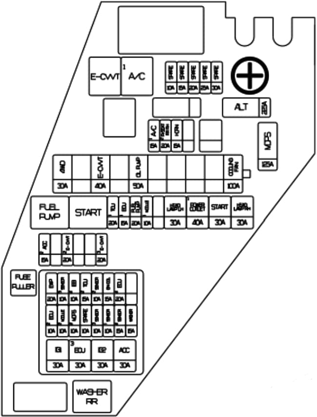
| Fuse Name | Amps | Circuit Protected |
|---|---|---|
| ALT | 225A | Alternator |
| MDPS | 125A | MDPS Unit |
| COOLING FAN | 100A | Cooling Fan Motor |
| OIL PUMP | 50A | Electronic Oil Pump |
| E-CVVT | 40A | E-CVVT Relay |
| 4WD | 30A | 4WD ECU |
| HEAD LAMP RH | 30A | Head Lamp RH |
| START | 30A | Start Relay |
| POWER OUTLET 1 | 40A | E/R Sub Junction Block (Power Outlet 1 Relay) |
| HEAD LAMP LH | 30A | Head Lamp LH |
| HORN | 15A | PCB Block (Horn Relay) |
| P/SEAT RR RH 2 | 20A | 2ND Seat RH Reclining Folding Actuator, 2ND Seat RH Module |
| A/C1 | 15A | A/C Relay |
| MODULE 1 | 10A | EMC Solenoid LH/RH |
| FUEL PUMP | 20A | Fuel Pump Relay |
| ECU 1 | 15A | ECM |
| TCU 1 | 20A | TCM |
| E-CVVT 3 | 20A | 2.5LT-GDI: ECM |
| E-CVVT 2 | 20A | 2.5LT-GDI: ECM |
| IG 1 | 30A | IG1 Relay |
| ECU 3 | 30A | Engine Control Realy |
| IG 2 | 30A | IG2 Relay |
| ACC | 30A | ACC Relay |
| ECU 2 | 10A | ECM |
| M0DULE 2 | 10A | Front Radar, Front Corner Radar LH/RH, 4WD ECU, EMC Control Module |
| MDPS 2 | 10A | MDPS Unit |
| SPARE | 10A | Not Used |
| SENSOR 3 | 10A | 2.5L T-GDI: Oxygen Sensor (Up/Down) 3.5L T-GDI: Oxygen Sensor #1~#2 |
| SENSOR 1 | 10A | 2.5L T-GDI: Injector #1~#4, E/R Junction Block (Fuel Pump Relay) 3.5L T-GDI: Injector #1~#6 (MPI), E/R Junction Block (Fuel Pump Relay) |
| SENSOR 4 | 15A | Cooling Fan Motor |
| WASHER | 15A | Washer Relay, E/R Junction Block (Washer RR Relay) |
| EWP | 20A | Electronic Water Pump |
| SENSOR 5 | 10A | Electronic Oil Pump |
| IEB4 | 10A | IEB Unit |
| TCU2 | 15A | P/N Relay, TCM |
| SENSOR 2 | 10A | 2.5L T-GDI: E/R Junction Block (A/C1 Relay), Oil Control Valve (Exhaust), Oil Pump Solenoid Valve, Purge Control Solenoid Valve, RCV Control Solenoid Valve, Canister Close Valve 3.5L T-GDI: E/R Junction Block (A/C 1 Relay), RCV Control Solenoid Valve #1/#2, Purge Control Solenoid Valve, Oil Pump Solenoid Valve, Oxygen Sensor #3/#4, Oil Control Valve #1—#4, Canister Close Valve |
| IGN COIL | 15A | 2.5L T-GDI: Ignition Coil #1~#4 3.5L T-GDI: Ignition Coil #1~#6 |
| ECU 4 | 20A | ECM |
Engine Compartment Fuse Box #2 Diagram
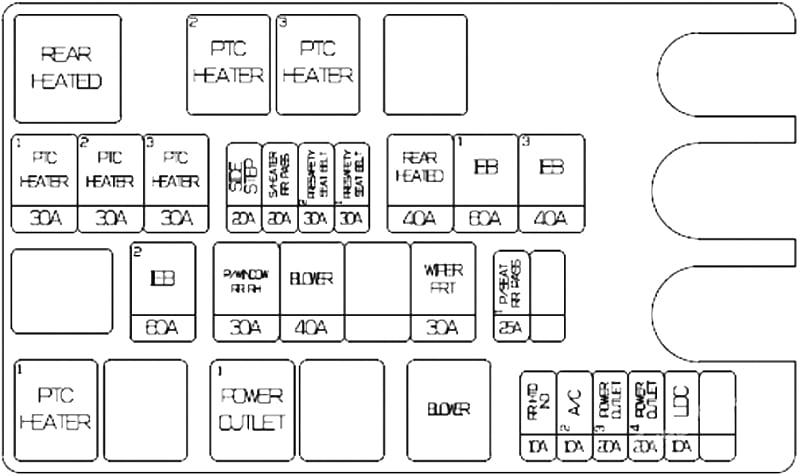
| Fuse name | Amps | Circuit protected |
|---|---|---|
| REAR HEATED | 40A | Rear Heated Relay (Relay 1) |
| IEB 1 | 60A | IEB Unit |
| IEB 3 | 40A | IEB Unit |
| IEB 2 | 60A | IEB Unit |
| P/WINDOW RR RH | 30A | Passenger Power Window Module, Rear Power Window Module RH |
| BLOWER | 40A | Blower Relay |
| WIPER FRT | 30A | Wiper Motor |
| SIDESTEP | 20A | Not Used |
| S/HEATER RR PASS | 20A | 2ND Seat RH Module, 2ND Air Ventilation Seat RH Control Module, 2ND Seat RH Warmer Control Module |
| PRESAFETY SEAT BELT 2 | 30A | Pre-Active Seat Belt Unit |
| PRESAFETY SEAT BELT 1 | 30A | Pre-Active Seat Belt Unit |
| P/SEAT RR PASS 1 | 25A | 2ND Seat RH Module |
| RR HTD IND | 10A | Front A/C Controller |
| A/C 2 | 10A | Front A/C Control Module |
| POWER OUTLET 3 | 20A | Luggage Power Outlet |
| POWER OUTLET 4 | 20A | Rear Console Power Outlet |
| LDC | 10A | Front Corner Radar LH/RH, Rear Corner Radar LH/RH, Head-Up Display, Smart Phone Wireless Charger, Instrument Cluster, Front A/C Controller, Front Console Keyboard, Rear A/C Control Panel |
Luggage Compartment Fuse Box Diagram
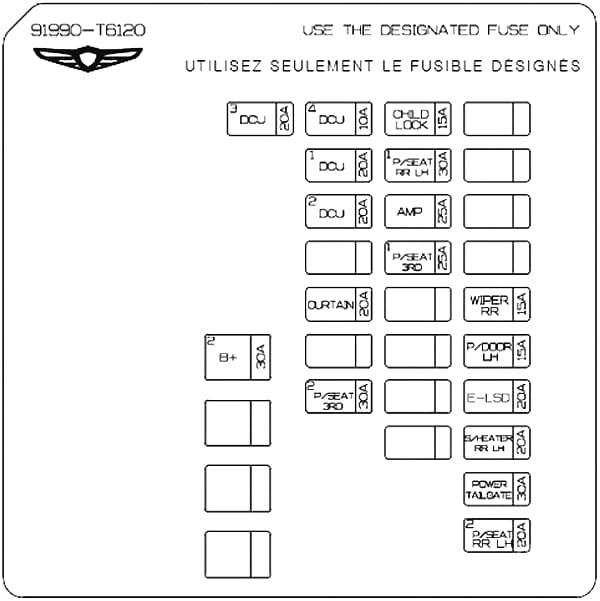
| Fuse Name | Amps | Circuit Protected |
|---|---|---|
| B+2 | 30A | ICU Junction Block (IPS2, IPS5, Fuse – AIR BAG 1, E-SHIFTER 1, IBU 1, SPARE (B+), P/DOOR RH, MODULE 5) |
| CHILD LOCK | 15A | Child Lock/Unlock Relay |
| P/SEAT RR LH 1 | 30A | 2ND Seat LH Module |
| AMP | 25A | AMP, Low DC-DC Converter (AMP) |
| P/SEAT 3RD 1 | 25A | 3RD Seat LH/RH Reclining Folding Actuator |
| CURTAIN | 20A | Rear Door Curtain Module |
| WIPER RR | 15A | Rear Wiper Relay, Rear Wiper Motor |
| P/DOOR LH | 15A | Driver Door Latch, Rear Door Latch LH |
| P/SEAT 3RD 2 | 30A | 3RD Seat Module |
| E-LSD | 20A | ELSD Control Module |
| S/HEATER RR LH | 20A | 2ND Seat LH Module, 2ND Air Ventilation Seat LH Control Module, 2ND Seat LH Warmer Control Module |
| POWER LIFTGATE | 30A | Power Liftgate Unit |
| P/SEAT RR LH 2 | 20A | 2ND Seat LH Reclining Folding Actuator, 2ND Seat LH Module |
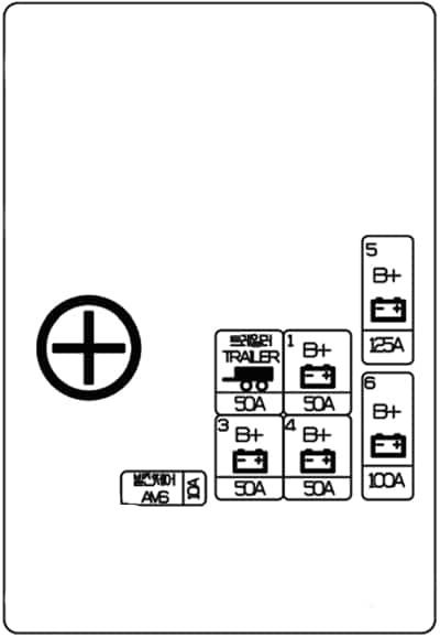
Battery junction block
| Fuse Name | Amps | Circuit Protected |
|---|---|---|
| B+ 5 | 125A | E/R SUB Junction Block (B+) |
| B+ 6 | 100A | Rear Junction Block (Fuse – B+2, E-LSD, POWER LIFTGATE, CURTAIN, P/SEAT 3RD 2, P/SEAT RR LH 2, P/SEAT RR LH 1, S/HEATER RR LH, P/DOOR LH, AMP, WIPER RR, CHILD LOCK, P/SEAT 3RD 1) |
| B+ 1 | 50A | ICU Junction Block (Long Term Load Latch Relay, Short Term Load Latch Relay, IPS1, IPS3, IPS4, IPS6, IPS7, Fuse – BRAKE SWITCH) |
| TRAILER | 50A | Trailer Connector |
| B+ 4 | 50A | ICU Junction Block (Fuse – TRAILER, INVERTER, P/SEAT PASS 2, DOOR LOCK, MODULE 4) |
| B+ 3 | 50A | ICU Junction Block (Fuse – SUNROOF 1, P/SEAT DRV 1, P/SEAT DRV 2, S/HEATER DRV, S/HEATER PASS, P/SEAT PASS 1, POWER HANDLE P/WINDOW LH, ECS. P/SEAT) |
| AMS | 10A | Battery Sensor |
WARNING: Terminal and harness assignments for individual connectors will vary depending on vehicle equipment level, model, and market.