Holden Apollo (JM/JP; 1993 – 1997) – fuse box diagram
Year of production: 1993, 1994, 1995, 1996, 1997, 1998
Passenger Compartment Fuse Block
There are two fuse boxes here, the first is behind the cover on the driver’s side instrument panel and the second is in the passenger’s side kick panel.
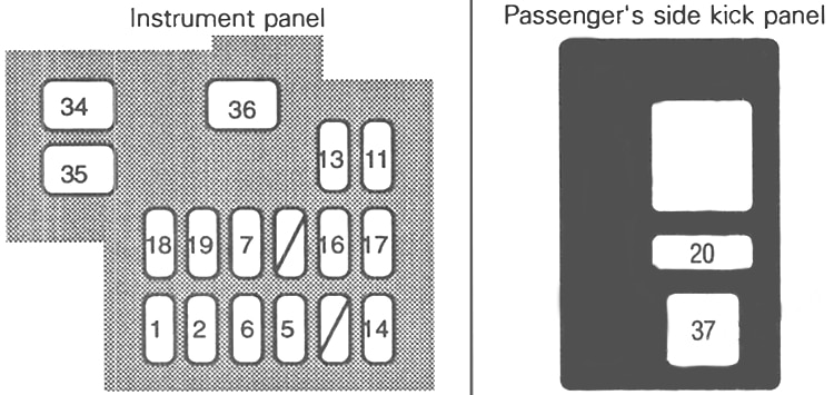
| № | Fuse Name | Amps | Function |
|---|---|---|---|
| 1 | ECU-IG | 15A | Electronically controlled automatic transmission system, cruise control system, anti-lock brake system, security system |
| 2 | GAUGE | 10A | Gauges and meters, backup light, air conditioning control system, rear window defogger, warning lights, engine and ECT ECU |
| 5 | WIPER | 20A | Windshield wipers and washers |
| 6 | TURN | 7.5A | Turn signal lights and emergency flashers |
| 7 | IGN | 7.5A | Engine and ECT ECU, charging system |
| 11 | ECU-B | 15A | Anti-lock brake system, engine and ECT ECU |
| 13 | STOP | 20A | Stop lights, cruise control system, anti-lock brake system, engine and ECT ECU |
| 14 | CIG | 15A | Audio system, clock, cigarette lighter, exterior mirror |
| 15 | – | – | Not used |
| 16 | TAIL | 15A | Tail lights, parking lights, licence plate lights, instrument panel light |
| 17 | – | – | Not used |
| 18 | SPARE | Spare fuse | |
| 19 | SPARE | Spare fuse | |
| 20 | A/C | 10A | Air conditioning control system |
| 34 | P/W | 30A | Power windows, power door lock control system, security system |
| 35 | DEFOG | 40A | Rear window defogger |
| 36 | AM 1 | 40A | Starting system, cigarette lighter, wipers, gauges, turning lights, engine ECT ECU |
| 37 | HTR | 40A | Air conditioning control system |
Engine Compartment Fuse Box
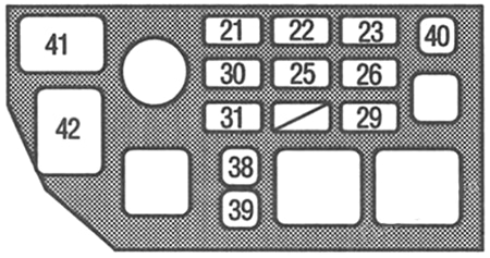
| № | Fuse Name | Amps | Function |
|---|---|---|---|
| 21 | STARTER | 10A | Starter system, engine and ECT ECU |
| 22 | ALT-S | 7.5A | Charging system |
| 23 | EFI | 15A | Engine and ECT ECU, fuel pump, security system |
| 25 | DOME | 20A | Audio system, interior light, clock, ignition switch light, trunk room light, security system |
| 26 | HAZ-HORN | 15A | Turn signal lights, emergency flasher, horn, security system |
| 29 | AM2 | 30A | Igniter |
| 30 | HEAD (RH) | 15A | Right-hand headlight |
| 31 | HEAD (LH) | 15A | Left-hand headlight |
| 34 | P/W | 30A | Power windows, power door lock control system, security system |
| 35 | DEFOG | 40A | Rear window defogger |
| 38 | CDS | 30A | Condenser cooling fan |
| 39 | FAN | 30A | Radiator cooling fan |
| 40 | ST MAIN | 30A | Starting system, engine and ECT ECU |
| 41 | ALT | 100A | Charging systEJm, stop lights, heater, defogger, anti-lock braket system |
| 42 | A.B.S. | 60A | Anti-lock brake system |
WARNING: Terminal and harness assignments for individual connectors will vary depending on vehicle equipment level, model, and market.