
Holden Barina Hatch (TK; 2005 – 2008) – fuse box diagram
Year of production: 2005, 2006, 2007, 2008
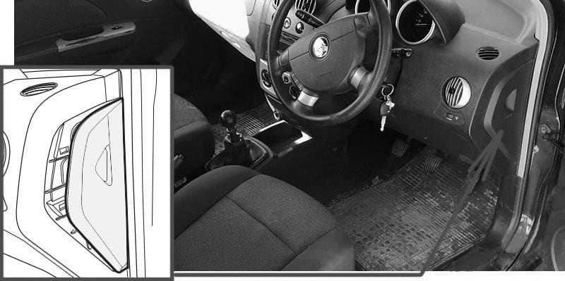
Passenger Compartment Fuse Box
Fuse Box Location
The fuses are located on the driver’s side wall of the instrument panel. To open the fuse cover, open the driver’s side door, pull the top of the cover out.
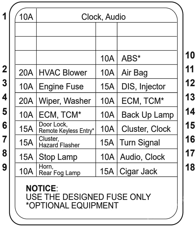
Fuse Box Diagram
| № | Amps | Circuits protected |
|---|---|---|
| 1 | 10A | Clock; Sound System |
| 2 | 20A | Blower Motor |
| 3 | 10A | Engine Fuse |
| 4 | 20A | Wiper; Washer |
| 5 | 10A | Electronic Control Module; Transmission Control Module (if fitted) |
| 6 | 15A | Door Lock; Remote Keyless Entry (if fitted) |
| 7 | 15A | Instrument Cluster; Hazard Warning Flasher |
| 8 | 15A | Stop Lamp |
| 9 | 10A | Horn; Rear Fog Lamp |
| 10 | 10A | Antilock Brake System (if fitted) |
| 11 | 10A | Air Bag |
| 12 | 15A | DIS; Injector (If fitted) |
| 13 | 10A | Electronic Control Module; Transmission Control Module (If fitted) |
| 14 | 10A | Backup Lamp |
| 15 | 10A | Instrument Cluster; Clock |
| 16 | 15A | Turn Signal |
| 17 | 10A | Audio; Clock |
| 18 | 15A | Cigar Lighter, Jack |
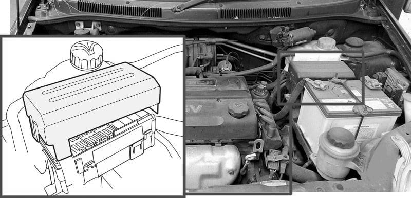
Engine Compartment Fuse Box
Fuse Box Location
The fuse box is located in the engine compartment next to the coolant reservoir. To remove the cover, release the catch on the side of the fuse box towards the engine and release the two tabs at the opposite side.
Fuse Box Diagram

| № | Amps | Circuits protected |
|---|---|---|
| 1 | 10A | Right High Beam Headlamp |
| 2 | 10A | Left High Beam Headlamp |
| 3 | 10A | Right Low Beam Headlamp |
| 4 | 10A | Left Low Beam Headlamp |
| 5 | 10A | Dome Lamp |
| 6 | 30A | Defogger |
| 7 | 20A | Parking Lamp |
| 8 | 25A | Headlamp |
| 9 | 10A | Air Conditioning Compressor |
| 10 | 30A | Blower |
| 11 | 30A | Interior Fuse Block |
| 12 | 30A | Ignition 2 |
| 13 | 30A | Ignition 1 |
| 14 | 10A | Right Parking Lamp |
| 15 | 10A | Left Parking Lamp |
| 16 | 20A | Sunroof |
| 17 | 10A | Horn |
| 18 | 15A | Fuel Pump |
| 19 | 15A | Front Fog Lamp |
| 20 | 60A | Anti-lock Brakes (ABS) |
| 21 | 30A | Radiator Fan |
| 22 | 20A | Main Relay (if fitted) |
| 23 | 30A | Power Window |
| 24 | High Beam Head lamp (Relay) | |
| 25 | Power Window (Relay) | |
| 26 | Main Relay / Fan Control Relay | |
| 27 | High Speed Radiator Fan (Relay) | |
| 28 | Low Speed Radiator Fan (Relay) | |
| 29 | Low Beam Head Lamp (Relay) | |
| 30 | Fog Lamp (Relay) | |
| 31 | Fuel Pump (Relay) | |
| 32 | Air Conditioning Compressor (Relay) | |
| 33 | Parking Lamp (Relay) | |
| 34 | Battery Positive Terminal | |
| 35 | Spare fuses (10A, 15A, 20A) |
WARNING: Terminal and harness assignments for individual connectors will vary depending on vehicle equipment level, model, and market.