Holden Captiva 7 (2006 – 2010) – fuse and relay box diagram
Year of production: 2006, 2007, 2008, 2009, 2010
The Holden Captiva / Captiva 7 (CG, pre-facelift) is a compact crossover SUV that was manufactured between 2006 and 2011. This article provides fuse box diagrams for the 2006, 2007, 2008, 2009, and 2010 models of the Holden Captiva. It also includes details about the location of the fuse panels within the vehicle and outlines the function and layout of each fuse and relay.
Passenger Compartment Fuse Box
Fuse Box Location
The fuses are located on the left-hand side of the driver’s side footwell. To open the fuse cover, pull the top of the cover outward.
Fuse Box Diagram
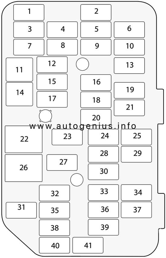
Assignment of the fuses in the passenger compartment
| № | Amps | Allocation |
|---|---|---|
| 1 | 10A | Front mirror |
| 2 | 20A | Door lock |
| 3 | Spare | |
| 4 | 15A | Front door lock |
| 5 | 15A | BCM (VB6) |
| 6 | 20A | APO 1 (Additional power outlet 1) |
| 7 | 20A | Cigar lighter |
| 8 | 20A | APO 2 (Additional power outlet 2) |
| 9 | 15A | BCM (VB3) |
| 10 | 20A | Heat/mat |
| 11 | 20A | Passenger power window |
| 12 | 15A | TCM |
| 13 | 15A | Audio |
| 14 | 20A | Driver’s power window |
| 15 | 15A | Engine |
| 16 | 15A | BCM (VB4) |
| 17 | 10A | XBCM |
| 18 | 15A | BCM (VB5) |
| 19 | 10A | 2006-2007: Trailer |
| 20 | 10A | 2006-2007: RR CLS |
| 21 | 10A | 2006-2007: PKLP-RH |
| 22 | Relay ACC/RAP | |
| 23 | 10A | Lift glass |
| 24 | 15A | Air conditioning |
| 25 | 10A | Air conditioning |
| 26 | Relay run/crank | |
| 27 | 15A | OSRVM HT |
| 28 | 20A | BCM (VB2) |
| 29 | 10A | 2006-2007: SSPS |
| 30 | 15A | BCM (VB7) |
| 31 | 10A | Clock |
| 32 | 10A | Instrument cluster |
| 33 | 2A | Ignition switch |
| 34 | 10A | BCM (VB1) |
| 35 | 10A | Ignition 1 |
| 36 | 10A | Rear defrost |
| 37 | 10A | 2006-2007: CTD Horn |
| 38 | 10A | Airbag |
| 39 | 10A | Airbag |
| 40 | 2A | 2006-2007: WHL S/W |
| 41 | 10A | Front washer |
Engine Compartment Fuse Box
Fuse Box Location
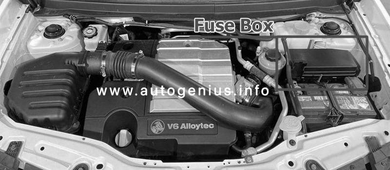
This fuse box is located on the passenger side of the engine compartment, it contains circuit fuses, main fuses and relays. To remove the cover, press the catch on the side of the fuse box toward the engine and release the two tabs at the opposite side.
Fuse Box Diagram
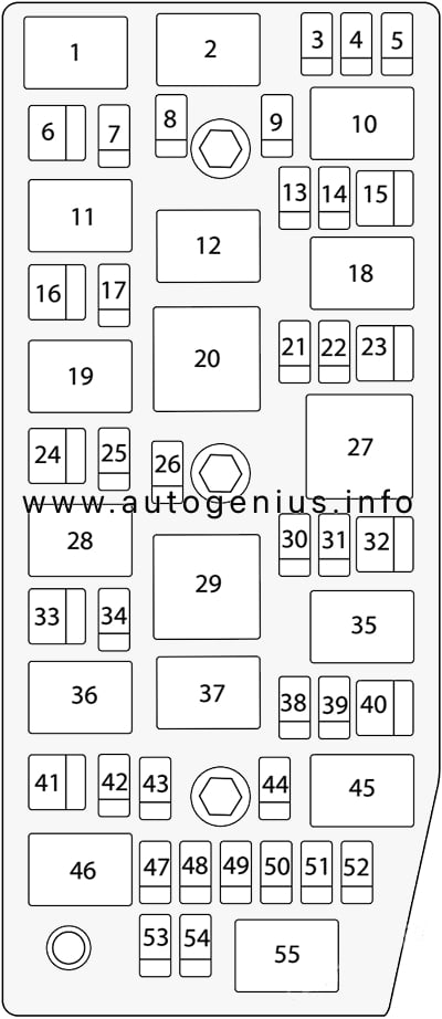
Assignment of the fuses in the engine compartment
| № | Amps | Allocation |
|---|---|---|
| 1 | Starter relay | |
| 2 | Main relay | |
| 3 | 20A | ECM |
| 4 | 15A | Engine 2 |
| 5 | 15A | Engine 1 |
| 6 | 20A | Starter |
| 7 | 10A | Main |
| 8 | 10A | A/C compressor |
| 9 | 15A | Engine 3 |
| 10 | Auxiliary fan relay | |
| 11 | A/C compressor relay | |
| 12 | Main fan relay | |
| 13 | 15A | AWD |
| 14 | 15A | Fuel |
| 15 | 30A | Main fan |
| 16 | 40A | ABS |
| 17 | 20A | ABS |
| 18 | Fuel relay | |
| 19 | Horn relay | |
| 20 | Fan control relay | |
| 21 | Spare | |
| 22 | 15A | Stop |
| 23 | 30A | Auxiliary fan |
| 24 | 40A | Run |
| 25 | 25A | Wiper |
| 26 | 15A | Horn |
| 27 | Wiper speed relay | |
| 28 | Wiper relay | |
| 29 | Run relay | |
| 30 | 15A | Anti theft |
| 31 | 20A | Sunroof |
| 32 | 40A | Accessory / lgnition |
| 33 | 60A | Battery |
| 34 | 30A | Power seat |
| 35 | Defog relay | |
| 36 | Front fog relay | |
| 37 | Park lamp relay | |
| 38 | 15A | H/light low RH |
| 39 | 15A | H/light low LH |
| 40 | 30A | Defog |
| 41 | 20A | Rear wiper |
| 42 | 15A | H/light high |
| 43 | 15A | Front fog |
| 44 | 10A | Park lamp LH |
| 45 | H/light low relay | |
| 46 | H/light high relay | |
| 47 | Spare | |
| 48 | Spare | |
| 49 | 10A | Park lamp RH |
| 50 | 15A | TCM |
| 51 | 20A | H/light washer |
| 52 | Spare | |
| 53 | Spare | |
| 54 | Spare | |
| 55 | H/light washer relay | |
| R1 | DRIVING LAMPS | |
| R2 | HEADLAMP WASHER | |
| R3 | REAR WASHER PUMP | |
| R4 | FRONT WASHER PUMP | |
| R5 | REAR DEMISTER | |
| R6 | FRONT WIPER CONTROL | |
| R7 | WIPER SPEED | |
| R8 | ENGINE CONTROL MODULE | |
| R9 | – | |
| R10 | INCLR PUMP | |
| R11 | – | |
| R12 | REAR WIPER CONTROL | |
| R13 | FOG LAMPS | |
| R14 | LOW BEAM HEADLAMPS | |
| R15 | HIGH BEAM HEADLAMPS | |
| R16 | STARTER | |
| R17 | RUN / CRANK | |
| R18 | BRAKE VACUUM PUMP | |
| R19 | AIR-CONDITIONING CONTROL | |
| R20 | HORN |
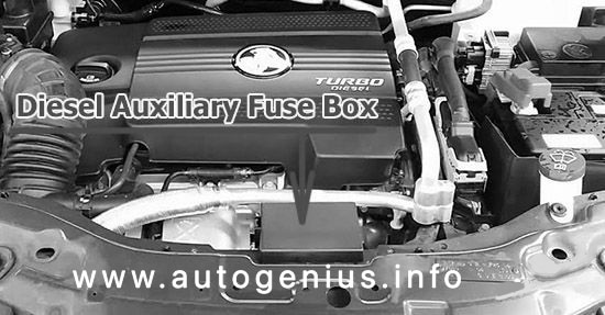
Diesel Auxiliary Fuse Box
Fuse Box Location
Fuse Box Diagram
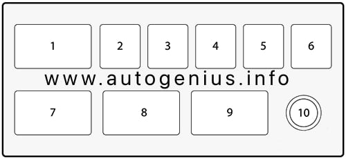
Assignment of the fuses in the auxiliary fuse box
| № | Amps | Allocation |
|---|---|---|
| 1 | Relay PTC 3 | |
| 2 | 40A | PTC 3 |
| 3 | 40A | PTC 2 |
| 4 | 40A | PTC 1 |
| 5 | 30A | F/F HTR |
| 6 | 60A | GPCU |
| 7 | Relay PTC 2 | |
| 8 | Relay PTC 1 | |
| 9 | Relay F/F HTR | |
| 10 | B+ |
WARNING: Terminal and harness assignments for individual connectors will vary depending on vehicle equipment level, model, and market.