Holden Combo (XC; 2001 – 2005) – fuse box diagram
Year of production: 2001, 2002, 2003, 2004, 2005
Engine Compartment Fuse Box
Fuse Box Location
The fuses are located between the passenger side headlamp and the coolant surge tank.
To open the fuse compartment, press the retaining clip towards the compartment lid and lift the lid upwards. Remove the lid completely to access the fuses.
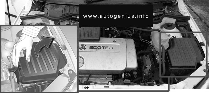
To help in replacing fuses, there is a special fuse gripping tool located beside the spare fuses in the fuse box.
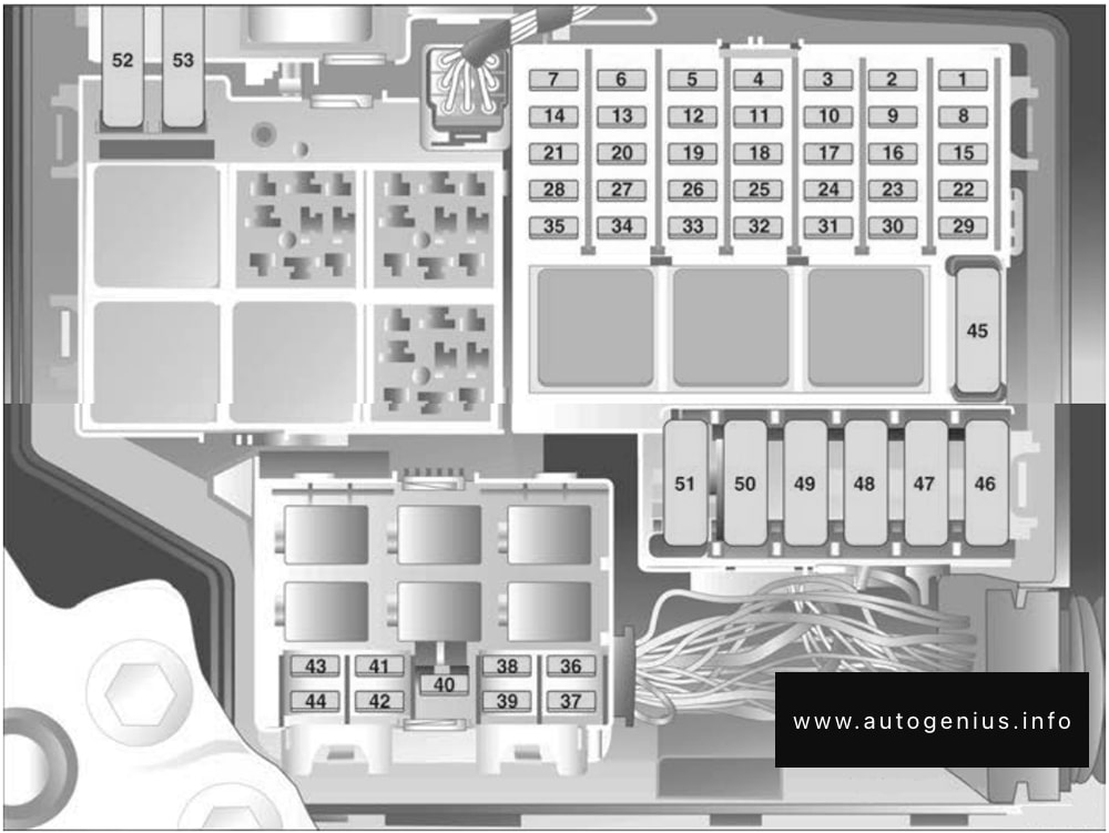
Fuse Box Diagram
| № | Amps | Function |
|---|---|---|
| 1 | 7.5A | Central control unit |
| 2 | 7.5A | Engine control unit |
| 3 | 7.5A | Instruments, horn, information display, hazard warning flashers |
| 4 | 5A | Number plate light |
| 5 | – | – |
| 6 | 10A | Automatic transmission (if fitted) |
| 7 | – | – |
| 8 | 10A | Starter |
| 9 | 20A | Fuel injection system, fuel pump |
| 10 | 10A | Horn |
| 11 | 15A | Central control unit |
| 12 | 15A | Information display, radio |
| 13 | – | – |
| 14 | – | – |
| 15 | 15A | Windscreen washer |
| 16 | 5A | Courtesy lamp |
| 17 | 20A | Central control unit |
| 18 | – | – |
| 19 | – | – |
| 20 | – | – |
| 21 | – | – |
| 22 | 20A | Central control unit |
| 23 | 20A | Windscreen wipers |
| 24 | 5A | Radio, information display courtesy lamp, instruments, EPS, immobiliser |
| 25 | 10A | Brake lights |
| 26 | 10A | Cigarette lighter |
| 27 | – | – |
| 28 | – | – |
| 29 | 20A | Windscreen washer system |
| 30 | 15A | Engine control unit |
| 31 | 15A | Air conditioning system (if fitted) |
| 32 | 10A | Heated rear window (if fitted) |
| 33 | – | – |
| 34 | – | – |
| 35 | 5A | Radio |
| 36 | 10A | Dipped beam (left) |
| 37 | 10A | Dipped beam (right) |
| 38 | 5A | Park and tail lights (left) |
| 39 | 5A | Park and tail lights (right) |
| 40 | – | – |
| 41 | – | – |
| 42 | 10A | Fog lights |
| 43 | 10A | Headlights – high beam (left) |
| 44 | 10A | Headlights – hiqh beam (right) |
| 45 | 30A | Air conditioning (if fitted) |
| 46 | 20A | Engine control unit |
| 47 | 30A | Heated rear window (if fitted) |
| 48 | 30A | Starter |
| 49 | 50A | EPS |
| 50 | – | – |
| 51 | – | – |
| 52 | 40A | Cooling fan (without air conditioninq) |
| 53 | 30A | Air conditioning cooling fan (if fitted) |
WARNING: Terminal and harness assignments for individual connectors will vary depending on vehicle equipment level, model, and market.