Holden Malibu (EM; 2013 – 2015) – fuse box diagram
Year of production: 2013, 2014, 2015
Passenger Compartment Fuse Box
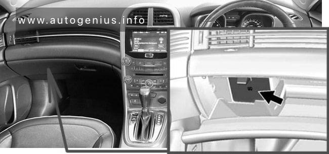
Fuse Box Location
The instrument panel fuse block is located inside the glove box. To access the fuses, open the fuse panel door by pulling down at the top.
Fuse Box Diagram
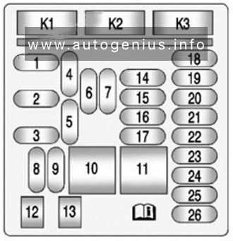
| № | Usage |
|---|---|
| 1 | Steering Wheel Controls Backlight |
| 2 | Left Mirror Turn Signal, Right Rear Turn Signal, Left Front Turn Signal, Headlamp Washer |
| 3 | Right Mirror Turn Signal, Left Brake Lamp, Right Front Turn Signal, Left Rear Turn Signal |
| 4 | Radio |
| 5 | Universal Hands-Free Phone |
| 6 | Front Accessory Power Outlet |
| 7 | Console Bin Power Outlet |
| 8 | Number Plate Lamp, Centre High Mounted Brake Lamp, Rear Fog Lamps, Right Brake Lamp, Left Tail lamp, Hazard Switch Backlight, Boot Release, Indicator Light Dimming, Keyless Start Indicator Light, Windscreen Washer Pump |
| 9 | Left Low Beam Headlamp, Left Daytime Running Lamp |
| 10 | Power Door Locks (J-Case Fuse) |
| 11 | Front Heater Ventilation Air Conditioning / Blower (J-Case Fuse) |
| 12 | Passenger Seat (Circuit Breaker) |
| 13 | Driver Seat (Circuit Breaker) |
| 14 | Diagnostic Link Connector |
| 15 | Airbag, SDM |
| 16 | Boot Release |
| 17 | Heater Ventilation Air Conditioning Controller |
| 18 | Audio Main |
| 19 | Displays |
| 20 | Spare |
| 21 | Instrument Panel Cluster |
| 22 | Ignition Switch |
| 23 | Right Low Beam Headlamp, Right Daytime Running Lamp |
| 24 | Ambient Lighting, Boot Lamp, Switch Backlighting |
| 25 | Spare |
| 26 | Electric Steering Column Lock |
| Relays | |
| K1 | Boot Release |
| K2 | Not Used |
| K3 | Power Outlet Relay |
Engine Compartment Fuse Box
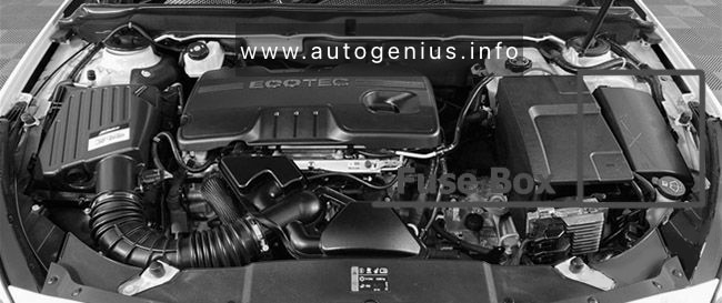
Fuse Box Location
The engine compartment fuse block is located on the passenger side of the engine compartment, near the battery.
Fuse Box Diagram

| № | Usage |
|---|---|
| Mini Fuses | |
| 1 | Transmission Control Module Battery |
| 2 | Engine Control Module Battery |
| 3 | Air Conditioning Compressor Clutch |
| 5 | Engine Control Module Ignition |
| 8 | Coil Even |
| 9 | Coil Odd |
| 10 | Engine Control Module |
| 11 | Non Walk Veh |
| 13 | Transmission / Fuel System Control Module Ignition |
| 14 | Low Beam / DRL Right |
| 16 | PT Run/Crank Ignition |
| 17 | SDM Ignition |
| 18 | Vehicle Air Purification System |
| 20 | Fuel Pump |
| 23 | Variable Effort Steering |
| 29 | Left Seat Power Lumber Control |
| 30 | Right Seat Power Lumber Control |
| 31 | Trailer |
| 32 | VCM VBATT 06 |
| 33 | Front Heated Seats |
| 34 | Antilock Brake System Valve |
| 35 | Amplifier |
| 36 | AFL/AHL Motor |
| 37 | Right Main Beam |
| 38 | Left Main Beam |
| 46 | Term 87A |
| 47 | Non Walk 02 |
| 48 | Fog lamp |
| 49 | Right HID Low Beam |
| 50 | Left HID Low Beam |
| 51 | Horn |
| 52 | MIL Ignition |
| 53 | Body Run/Crank |
| 54 | IP Run/Crank |
| 55 | Front Power Windows / Mirrors |
| 56 | Windscreen Washer Pump |
| 57 | Ign Not R/C Electric Steering Column Lock |
| 60 | Heated Mirror |
| 62 | Canister Vent Solenoid |
| 64 | Adaptive Forward Lighting / Headlamp Levelling Electric |
| 65 | Anti-Theft Warning Siren Horn |
| 67 | Fuel System Control Module |
| 69 | Battery Voltage Sensor |
| 70 | Rain Sensor, Lane Departure Warning, Ultrasonic Park Assist |
| 71 | PEPS Battery |
| J-Case Fuses | |
| 6 | Front Wiper |
| 12 | Starter |
| 21 | Rear Power Window |
| 22 | Sunroof |
| 24 | Front Power Window |
| 25 | PEPS Motor |
| 26 | Antilock Brake System Pump |
| 27 | Electric Parking Brake |
| 28 | Rear Window Demister |
| 41 | Brake Vacuum Pump |
| 42 | Cooling Fan K2 |
| 43 | Heated Rear Seats |
| 44 | Headlamp Washer |
| 45 | Cooling Fan K1 |
| 59 | Diesel Fuel Heater |
| Relays | |
| 1 | Air Conditioning Compressor Clutch |
| 2 | Starter |
| 3 | Cooling Fan K7 |
| 4 | Front Wiper Speed |
| 5 | Front Wiper On/Off |
| 6 | Dipped Beam DRL Right |
| 7 | Powertrain |
| 8 | Fuel Pump |
| 9 | Cooling Fan K2 |
| 10 | Cooling Fan K3 |
| 11 | Headlamp Washer |
| 12 | Cooling Fan K3 |
| 13 | Cooling Fan K1 |
| 14 | Dipped Beam HID / Left DRL |
| 15 | Run/Crank |
| 16 | Diesel Fuel Heater |
| 17 | Window / Mirror Demister |
WARNING: Terminal and harness assignments for individual connectors will vary depending on vehicle equipment level, model, and market.