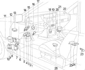
Infiniti M30 (1990 – 1992) – fuse box diagram
Year of production: 1990, 1991, 1992
Passenger Compartment

- Ignition Relay No.1
- Door Lock Relay
- Accessory Relay No.2
- Ignition Relay No.2
- Accessory Relay No.1
- Automatic Transmission Control Unit
- Time Control Unit
- Door Lock Timer No.1
- Rear Window defogger Relay
- Circuit Breaker (Power Door Lock, Power Seat)
- Theft Warning Control Unit
- Door Lock Timer No.2
- Shift Lock Control Unit
- Stop Lamp Switch
- Automatic Speed Control Device (ASCD) Cancel Switch
- Combination Flasher Unit
- Kickdown Switch
- Blower Relay (High Speed – Automatic A/C)
Blower Relay (Manual A/C) - Warning Chime
- Electronic Concentrated Engine Control (ECCS) Relay
- Electronic Concentrated Engine Control (ECCS) Control Unit
- Safety Relay
- Speed Sensor (on rear extension)
- Tunnel Sensor and Safing Sensor
- Air Bag Control Unit
- Power Window Amplifier
Passenger Compartment Fuse Box
| No. |
A |
Circuit Protected |
| 1 | 15 | Headlamp, Theft Warning System |
| 2 | 15 | Headlamp, Theft Warning System |
| 3 | 15 | Clearance Lamps, Tail Lamps, License Lamps, Side Marker Lamp, Illumination Lamps, Glove Box Lamp |
| 4 | 10 | Spot Lamp, Vanity Lamp, Trunk Room Lamp, Interior Lamp, Step Lamp, Key Illumination, Time Control System, Automatic Transmission Control Unit, Theft Warning System, Automatic Air Conditioner, Illuminated Entry System, Audio (except Bose), Air Bag System |
| 5 | 10 | Hazard Warning |
| 6 | 15 | Stop Lamp, Shift Lock Control System, Automatic Speed Control Device |
| 7 | 10 | Horn, Theft Warning System |
| 8 | 15 | Blower Motor, Automatic A/C Amplifier |
| 9 | 15 | Blower Motor, Automatic A/C Amplifier |
| 10 | 10 | Audio, Power Antenna |
| 11 | 20 | Rear Window Defogger |
| 12 | 20 | Rear Window Defogger |
| 13 | 10 | Warning Lamp, Meter, Gauge, Time Control System, Automatic Air Conditioner, Automatic Speed Control Device, Rear Window Defogger, Power Antenna, Power Window, Air Bag System |
| 14 | 10 | Hazard Warning |
| 15 | 10 | Shift Lock Control System, Automatic Transmission Control Unit, Theft Warning System, ABS, Sonar Suspension System |
| 16 | 10 | Air Bag System |
| 17 | 10 | Electronic Concentrated Engine Control (ECCS) |
| 18 | 20 | Wiper and Washer |
| 19 | 15 | Cigarette Lighter |
| 20 | 10 | Door Mirror, Manual Air Conditioner, Theft Warning System, Time Control System, Clock |
- Sonar Suspension Control Unit
- Audio Amplifier
- ABS Control Unit
- Fuel Pump Relay
- Trunk Lid Opener Relay
- Fuel Filler Lid Opener Relay
- Automatic Speed Control Device (ASCD) Control Unit
- Automatic Speed Control Device Hold Relay
Engine Compartment
- Fuse Box
- Battery
- Relay Box
- Dropping Resistor
- Automatic Speed Control Device (ASCD) Pump
- Automatic Speed Control Device Actuator
- ABS Actuator
- Wiper Motor
- Ignition Coil
- Left Crash Zone Sensor
- Fusible Link
- Center Crash Zone Sensor
- Starter Relay
- Right Crash Zone Sensor
- Sonar Road Surface Sensor (for Sonar Suspension System)
Engine Compartment Fuse Box
| No. |
A |
Circuit Protected |
| 1 | 20 | ABS |
| 2 | 10 | Time Control System, Shift Lock Control System |
| 3 | 10 | Electronic Concentrated Engine Control (ECCS), Radiator Fan Relay |
| 4 | 20 | Trunk Lid Opener, Fuel Filler Lid Opener |
| 5 | 15 | BOSE Amplifier |
| 6 | 15 | BOSE Amplifier |
| 7 | – | ABS |
| 8 | – | Ignition Switch |
| 9 | – | – |
| 10 | – | Circuit Breaker (Power Door Lock, Power Seat) |
| 11 | – | Electronic Concentrated Engine Control (ECCS) |
| 12 | – | Radiator Fan |
| Relay | ||
| R1 | Horn | |
| R2 | Radiator Fan | |
| R3 | Inhibitor | |
| R4 | Air Conditioner | |
| R5 | Wiper | |
Engine Compartment Relay Box
box diagram – engine compartment relay box
| No. |
Circuit Protected |
| R1 | Theft Warning (No.1) |
| R2 | Theft Warning (No.2) |
| R3 | Theft Warning (No.3) |
| R4 | Theft Warning Horn |
| R5 | Switching |
WARNING: Terminal and harness assignments for individual connectors will vary depending on vehicle equipment level, model, and market.