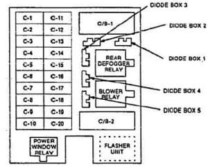
Isuzu Trooper (1992 – 1994) – fuse box diagram
Year of production: 1992, 1993, 1994
Fuse box diagram

| Number | A | Function |
| C-1 | 10 | Staning system, blower comrots: A/C: compressor controls |
| C-2 | — | — |
| C-3 | 15 | Back up lights; turn lights; hazard lights; cornering lights |
| C-4 | 10 | Rear defogger; cruise control; power windows; electronic engine control; door mirror defogger; automatic transmission control; shift interlock system; power sunroof |
| C-5 | 15 | Windshield wiper/washer |
| C-6 | 10 | Rear wiper/washer |
| C-7 | 10 | Headlight wiper/washer |
| C-8 | 15 | Electronic engine control; charging system |
| C-9 | 15 | lgniton system |
| C-10 | 7,5 | Gauges: indicators |
| C-11 | 10 | Sound system; power mirrors; anti-theft system |
| C-12 | 20 | Cigarette lighter; anti·theft system |
| C-13 | 15 | Lighting switch details |
| C-14 | 15 | Brake lights; automatic transmission control; shift interlock system; rear wheel anti-lock (RWAL); brake system |
| C-15 | 15 | Hazard lights; horns; anti-theft system |
| C-16 | 25 | Rear defogger |
| C-17 | 7,5 | Sound system; Interior lights; key-in ignition warning system; anti-theft system; auto antenna |
| C-18 | 20 | Automatic door locks; anti·theft system |
| C-19 | 25 | Blower controls |
| C-20 | — | — |
| Circuit Breaker Number | A | Function |
| C/B-1 | 20 | Power windows; power sunroof |
| C/B-2 | — | — |
WARNING: Terminal and harness assignments for individual connectors will vary depending on vehicle equipment level, model, and market.
