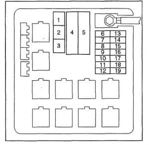
Isuzu VehiCROSS (1999 – 2001) – fuse box diagram
Year of production: 1999, 2000, 2001
Engine compartment
Fuses

 Isuzu VehiCROSS – fuse box diagram – fuse
| No |
A |
Description |
| 1 |
40 |
ABS |
| 2 |
40 |
PCM |
| 3 |
30 |
Condenser Fan |
| 4 |
100 |
Main |
| 5 |
60 |
Key SW |
| 6 |
|
EB-1 |
| 7 |
|
EB-2 |
| 8 |
|
EB-3 |
| 9 |
|
EB-4 |
| 10 |
|
EB-5 |
| 11 |
|
EB-6 |
| 12 |
|
EB-7 |
| 13 |
|
EB-8 |
| 14 |
|
EB-9 |
| 15 |
|
EB-10 |
| 16 |
|
EB-11 |
| 17 |
|
EB-12 |
| 18 |
|
EB-13 |
| 19 |
|
EB-14 |
 Isuzu vehiCROSS – fuse box diagram – relay
| No |
Relay |
| 1 |
Headlight relay |
| 2 |
— |
| 3 |
Fuel Pump Relay |
| 4 |
Horn Relay |
| 5 |
Thermo Relay |
| 6 |
Heater Relay |
| 7 |
Starter Relay |
| 8 |
Starter Cut Relay |
| 9 |
PCM Main Relay |
| 10 |
A/C Compressor Relay |
Fuse & Relay Box, I/P
 Isuzu VehiCROSS – fuse box diagram – I/P
| No |
Description |
| 21 |
CB-1 |
| 22 |
CB-2 |
| 23 |
CB-3 |
| 24 |
CB-4 |
| 25 |
CB-5 |
| 26 |
CB-6 |
| 27 |
CB-7 |
| 28 |
CB-8 |
| 29 |
CB-9 |
| 30 |
CB-10 |
| 31 |
CB-11 |
| 32 |
CB-12 |
| 33 |
CB-13 |
| 34 |
CB-14 |
| 35 |
CB-15 |
| 36 |
CB-16 |
| 37 |
CB-17 |
| 38 |
CB-18 |
| 39 |
CB-19 |
| 40 |
CB-20 |
| 41 |
CB-21 |
| 42 |
CB-22 |
WARNING: Terminal and harness assignments for individual connectors will vary depending on vehicle equipment level, model, and market.
