JCB 2CX – fuse box diagram
Year of production:
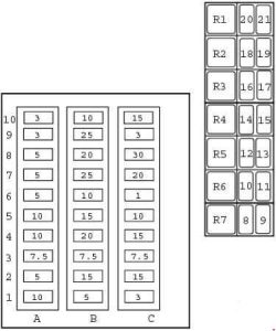
Fuse box diagram

| Number | Ampers | Protected circuit |
| A1 | 10 | Junction box, hydraulic tools |
| A2 | 5 | Engine shut off system |
| A3 | 7,5 | Direction indicators |
| A4 | 10 | Creep speed transmission |
| A5 | 10 | Manual transmission |
| A6 | 5 | Airmaster (if fitted) |
| A7 | 5 | Shovel reset, Smooth ride system |
| A8 | 5 | Brake lights (secondary) |
| A9 | 3 | Right hand side lights |
| A10 | 3 | Left hand side lights |
| B1 | 5 | Tachometer, Gauges |
| B2 | 15 | Front horn, Front washer/wiper |
| B3 | 7,5 | Rear horn |
| B4 | 20 | Auxiliary power socket |
| B5 | 15 | Rear washer/wiper |
| B6 | 10 | Brake lights (primary) |
| B7 | 25 | Rear work lights |
| B8 | 20 | Lighting, headlights |
| B9 | 25 | Front work lights |
| B10 | 10 | Beacon |
| C1 | 3 | Rear fog light |
| C2 | 15 | Headlight dip beam |
| C3 | 7,5 | Sidelights |
| C4 | 15 | Hazard lights |
| C5 | 10 | Wiper, Face level fan, Interior light |
| C6 | 1 | Radio, Hourmeter |
| C7 | 20 | Thermostart |
| C8 | 30 | Heater, Air conditioning |
| C9 | 3 | Starter relays |
| C10 | 15 | Headlight main beam |
| Relay | ||
| R1 | Indicators | |
| R2 | Front working lights | |
| R3 | Rear working lights | |
| R4 | Starter 1 | |
| R5 | Starter 2 | |
| R6 | Buzzer | |
| R7 | Neutral start | |
| R8 | — | |
| R9 | Compressor interlock (Airmaster only) | |
| R10 | Compressor shutdown (Airmaster only) | |
| R11 | Compressor start (Airmaster only) | |
| R12 | Parking brake | |
| R13 | Transmission dump | |
| R14 | Transmission reverse | |
| R15 | Transmission forward | |
| R16 | Rear horn | |
| R17 | Lights | |
| R18 | Brake lights | |
| R19 | — | |
| R20 | — | |
| R21 | — | |
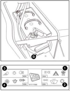
Link Box Fuses
To further protect the machine wiring harnesses and electrical circuits, a fuse link box is fitted to the battery, as shown at B.

| Number | Ampers | Protected circuit |
| 1 | 40 | Hazard warning lights, Side lights, Face level fan |
| 2 | 50 | Wash/Wipe, Transmission, Indicators |
| 3 | 60 | Work lights, Fog Lights, Road lights |
| 4 | 50 | Ignition, Heater, Thermostart |
WARNING: Terminal and harness assignments for individual connectors will vary depending on vehicle equipment level, model, and market.
