Jeep Grand Cherokee ZJ/ZG (1996 – 1998) – fuse and relay box diagram
Year of production: 1996, 1997, 1998
This article focuses on the post-facelift first-generation Jeep Grand Cherokee (ZJ), manufactured between 1996 and 1998. It provides fuse box diagrams for the 1996, 1997, and 1998 models, details the locations of the fuse panels within the vehicle, and explains the purpose of each fuse (fuse layout) and relay.
Passenger compartment fuse box
Fuse Box Location
It is located behind the lid under the glove compartment.
Fuse Box Diagram
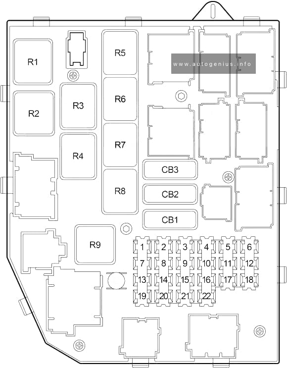
Assignment of the fuses and relay under the dashboard
| № | Amp Rating | Description |
|---|---|---|
| 1 | 10 | Radio |
| 2 | 15 | Cigar Lighter Relay |
| 3 | 10 | Rear Wiper/Washer Switch, Body Control Module |
| 4 | 10 | Airbag Control Module |
| 5 | 10 | Instrument Cluster, Shift Interlock (Gasoline), Lamp Outage Module |
| 6 | 15 | Back-Up Lamp Switch (Diesel), Vehicle Information Center, Graphic Display Module (Mini Overhead Console), Park/Neutral Position Switch, Speed Proportional Steering Module, Headlamp Leveling Switch, Combination Flasher, Automatic Day/Night Mirror, Overhead Console |
| 7 | 20 | Data Link Connector, Body Control Module, Automatic Headlamp Light Sensor/VTSS LED, Instrument Cluster, Power Amplifier |
| 8 | 20 | Rear Wiper Motor, Liftglass Limit Switch, Trailer Tow Connector, Trailer Tow Circuit Breaker |
| 9 | 15 | Stop Lamp Switch |
| 10 | 10 | Rear Window Defogger Switch |
| 11 | 10 | ABS |
| 12 | 10 | A/C Heater Control (MTC), Blend Door Actuator (MTC), Automatic Temperature Control Module (ATC), Recirculation Door Actuator (ATC), Driver/Passenger Seat Heater Control Module, Switch POD |
| 13 | 15 | Combination Flasher, Powe Antenna Relay |
| 14 | 15 | Cigar Lighter, Cigar Lighter Relay |
| 15 | 10 | Rear Fog Lamp Relay |
| 16 | 10 | Dome/Reading Lamp, Overhead Console, Underhood Lamp, Cargo Lamp, Glove Box Lamp, Courtesy Lamp, Key-In Switch/Halo Lamp, Visor/Vanity Lamp, Courtesy Lamp Relay |
| 17 | 15 | Headlamp Switch, Park Lamp Relay (Front Park Lamp, Body Control Module, Headlamp Switch, Lamp Outage Module, Radio, Vehicle Information Center) |
| 18 | 15 or 20 | 1998: Headlamp Dimmer Switch (gasoline – 15A, Diesel – 20A) |
| 19 | 15 | 1996-1997: Headlamp Dimmer Switch |
| 20 | 15 | Automatic Temperature Control Module (ATC), Radio, Vehicle Information Center, Graphic Display Module (Mini Overhead Console) |
| 21 | 15 | Power Outlet |
| 22 | 10 | Airbag Control Module |
| Circuit Breakers | ||
| CB1 | 20 | Intermittent Wiper Switch, Intermittent Wiper Relay, Wiper Motor, Sunroof Control Module, Sunroof Switch |
| CB2 | 30 | Driver/Passenger Door Module |
| CB3 | 20 | Power Seat, Seat Heater, Memory Seat Module |
| Relays | ||
| R1 | Power Antenna | |
| R2 | Combination Flasher | |
| R3 | Courtesy Lamp | |
| R4 | Rear Fog Lamp | |
| R5 | Auto Headlamp | |
| R6 | Park Lamp | |
| R7 | Cigar Lighter | |
| R8 | Front Fog Lamp | |
| R9 | Rear Window Defogger | |
Engine compartment fuse box
Fuse Box Diagram
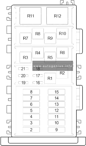
Assignment of the fuses and relay in the engine compartment
| No. | A | Description |
|---|---|---|
| 1 | 175 | Generator |
| 2 | 60 | ’98 (Max Cooling): Radiator Fan (High Speed) Relay, Radiator Fan (Low Speed) Relay, Diagnostic Connector |
| 3 | 40 | Rear Window Defogger Relay, Fuse (Engine Compartment): “21” |
| 4 | 30 | Diesel: Fuel Heater Relay |
| 5 | 50 | ’96-’97: ABS |
| 40 | ’98: ABS | |
| 6 | 20 | Horn Relay |
| 7 | 40 | Blower Motor (MTC, ATC), High Speed Blower Motor Relay (ATC), Blower Motor Module (ATC), Automatic Temperature Control Module |
| 8 | 40 | Starter Relay, Ignition Switch (Starter Relay, Clutch Interlock Switch (M/T), Fuse (Passenger Compartment): “1”, “2”, “3”, “4”, “5”, “6”, “11”, “12”, “22”, “CB1”; Fuse (Engine Compartment): “18”) |
| 9 | – | – |
| 10 | 20 | Fuse (Passenger Compartment): “14”, “15” |
| 11 | 50 | Fuse (Passenger Compartment): “7”, “8”, “9”, “CB2” |
| 12 | – | – |
| 13 | 30 | Headlamp Switch, Automatic Headlamp Relay, Daytime Running Lamp Module, Fuse (Passenger Compartment): “13” |
| 14 | 20 | ABS |
| 15 | 40 | Fuse (Passenger Compartment): “13”, “16”, “19”, “20”, “21”, “CB3” |
| 16 | 20 | Gasoline: Fuel Pump Relay |
| 15 | Diesel: Powertrain Control Module | |
| 17 | 15 | Transmission Control Relay |
| 18 | 15 | Gasoline: Automatic Shut Down Relay, Powertrain Control Module, Body Control Module, Air Conditioner Compressor Clutch Relay, Fuel Pump Relay, Duty Cycle EVAP/Purge Solenoid, Evaporative System Leak Detection Pump |
| 15 | Diesel: Fuel Heater Relay, Powertrain Control Module, MSA Controller, Body Control Module | |
| 19 | 20 | Front Fog Lamp Relay |
| 20 | 25 | Diesel: Automatic Shut Down Relay (Powertrain Control Module, Glow Plug Relay, EGR Solenoid, Generator, Mass Air Flow Module, Fuel Pump Module, MSA Controller) |
| 20 | Gasoline: Automatic Shut Down Relay (Fuel Injectors, Ignition Coils, Oxygen Sensors), Powertrain Control Module | |
| 21 | 15 | Air Conditioner Compressor Clutch |
| Relay | ||
| R1 | Transmission Control | |
| R2 | Horn | |
| R3 | Air Conditioner Compressor Clutch | |
| R4 | ABS Main | |
| R5 | – | |
| R6 | Automatic Shut Down | |
| R7 | Intermittent Wiper | |
| R8 | Starter | |
| R9 | – | |
| R10 | Fuel Pump | |
| R11 | Diesel: Fuel Heater | |
| R12 | ABS Pump | |
WARNING: Terminal and harness assignments for individual connectors will vary depending on vehicle equipment level, model, and market.