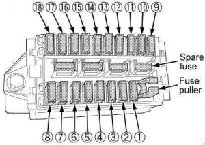
Kubota Tractor M9540 – fuse box diagram
Year of production:
Fuse box

 Kubota M9540 – fuse box diagram
| Number |
Ampere ratting [A] |
Protected circuit |
| 1 |
5 |
Starter Relay |
| 2 |
15 |
Auxiliary Power/Air Suspension Seat (if equipped) |
| 3 |
15 |
Work Light (Front, Side) |
| 4 |
10 |
Air Conditioner (Compressor) |
| 5 |
30 |
Air Conditioner (Fan Motor) |
| 6 |
15 |
Cigarette Lighter |
| 7 |
15 |
Work Light (Front) |
| 8 |
15 |
Work Light (Rear) |
| 9 |
20 |
Spare Fuse |
| 10 |
20 |
Flasher (Hazard) |
| 11 |
20 |
Head Light, Tail Lamp |
| 12 |
10 |
Meter, Radio (Back Up), Horn |
| 13 |
10 |
Turn Signal, Stop Lamp |
| 14 |
5 |
Meter Panel, OPC |
| 15 |
5 |
Alternator, Engine, Heater |
| 16 |
15 |
Wiper |
| 17 |
5 |
Air Conditioner (Control) |
| 18 |
5 |
Radio |
 Kubota M9540 – fuse box diagram
| Number |
Ampere ratting [A] |
Protected circuit |
| 19 |
100 |
Charge |
| 20 |
50 |
Air Heater |
| 21 |
50 |
Head Light, Hazard |
| 22 |
30 |
Work Light, Fuel Cut Solenoid |
| 23 |
30 |
Key Switch |
| 24 |
30 |
Electrical Outlet |
| 25 |
40 |
Air Conditioner |
 Kubota M9540 – fuse box diagram
| Number |
Ampere ratting [A] |
Protected circuit |
| 26 |
15 |
Air Suspension Seat (if equipped) |
 Kubota M9540 – fuse box diagram
| Number |
Ampere ratting [A] |
Protected circuit |
| 1 |
15 |
Work Light (R) |
| 2 |
15 |
Work Light (L) |
| 3 |
5 |
Alternator, Engine, Glow Plug |
| 4 |
5 |
Meter Panel, OPC |
| 5 |
10 |
Turn Signal |
| 6 |
15 |
Auxiliary Power |
| 7 |
5 |
Meter (Back Up) |
| 8 |
20 |
Head Light, Tail Lamp |
| 9 |
15 |
Flasher (Hazard) |
| 10 |
5 |
Starter Relay |
| 11 |
10 |
Horn |
 Kubota M9540 – fuse box diagram
| Number |
Ampere ratting [A] |
Protected circuit |
| 12 |
40 |
Key switch, Head Light, Hazard |
| 13 |
30 |
Fuel Cut Solenoid, Work Light |
| 14 |
50 |
Charge, Glow Plug |
WARNING: Terminal and harness assignments for individual connectors will vary depending on vehicle equipment level, model, and market.
