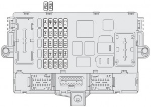
Lancia Musa FL (2007 – 2012) – fuse box diagram
Year of production: 2007, 2008, 2009, 2010, 2011, 2012
Fuse box on the dashboard

| User | Fuse | Ampere rating [A] |
| Right-hand dipped beam headlight | F12 | 15 |
| Left-hand dipped beam headlight / headlight aiming device | F13 | 15 |
| Reversing lights / engine compartment control box relay coils / body computer | F31 | 7,5 |
| +30 Driver’s / passenger’s door control units (*) | F32 | 15 |
| Left rear power window | F33 | 20 |
| Right rear power window | F34 | 20 |
| +15 Cruise control, signal from switch on brake pedal for control units (*) | F35 | 7,5 |
| +30 Presetting for trailer control unit, rear locks front locks with single door control unit (*) | F36 | 20 |
| +15 Third brake light, instrument panel, brake lights (*) | F37 | 10 |
| Boot unlocking | F38 | 15 |
| +30 EOBD diagnostic socket, sound system, navigator, tyre pressure control unit (*) | F39 | 10 |
| Rear heated screen | F40 | 30 |
| Heated door electric mirrors | F41 | 7,5 |
| +15 ABS / ESP control unit (*) | F42 | 7,5 |
| Windscreen wiper/washer | F43 | 30 |
| Cigar lighter / current socket on tunnel | F44 | 20 |
| Heated seats | F45 | 15 |
| Boot current socket | F46 | 20 |
| Driver’s door control unit power supply (power window, lock) | F47 | 20 |
| Passenger’s door control unit power supply (power window, lock) | F48 | 20 |
| +15 utilities (left and central dashboard control lights, electric mirrors, heated seat control lighting, presetting for radiotelephone, navigator, rain / daylight sensors, parking sensor control unit, sunroof control lighting) (*) | F49 | 7,5 |
| Airbag control unit | F50 | 7,5 |
| +15 Tyre pressure control unit, ECO / Sport control (*) | F51 | 7,5 |
| Rear screen wiper/washer | F52 | 15 |
| +30 Direction indicators, hazard lights, instrument panel (*) | F5 | 10 |
(*) +30 = battery directive positive terminal (not under key)
(*) +15 = positive terminal under key
Fuse box near the battery
| User | Fuse | Ampere ranting [A] |
| Dashboard control unit 1 | F1 | 70 |
| Power steering control unit | F2 | 70 |
| Ignition switch | F3 | 20 |
| Dashboard control unit 2 | F4 | 50 |
| ABS / ESP control unit | F5 | 50 |
| Radiator electric fan (low speed) (all versions) | F6 | 30 |
| Radiator electric fan (high speed) (all versions excluded 1.4 16V heated) | F7 | 40 |
| Climate control electric fan | F8 | 30 |
| Headlight washer | F9 | 20 |
| Horn | F10 | 15 |
| Electronic injection secondary services | F11 | 15 |
| Right main beam headlight | F14 | 10 |
| Left main beam headlight | F15 | 10 |
| Electronic injection primary services | F17 | 10 |
| +30 Engine control unit / Radiator electric fan remote control switch (1.9 Multijet) (*) | F18 | 7,5 |
| Compressor | F19 | 7,5 |
| Heated diesel oil filter (Multijet) | F20 | 30 |
| Fuel pump | F21 | 15 |
| Electronic injection primary services (1.4 16V) | F22 | 15 |
| Electronic injection primary services (Multijet) | F22 | 20 |
| Dual FuNction System gearbox oil pump | F23 | 15 |
| Dual FuNction System gearbox fuse box power supply (+ key) | F16 | 7,5 |
| +15 Electric power steering (*) | F24 | 7,5 |
| Front fog lights | F30 | 15 |
(*) +30 = battery directive positive terminal (not under key)
(*) +15 = positive terminal under key
Optional fusebox (on auxiliary bracket)
| User | Fuse | Ampere rating [A] |
| +30 Outside radio amplifier (*) | F34 | 15 |
| +30 Sunroof (*) | F58 | 20 |
(*) +30 = battery directive positive terminal (not under key)
(*) +15 = positive terminal under key
Fuses external to engine compartment fusebox
| User | Fuse | Ampere rating [A] |
| Dual FuNction System gearbox pump | F01 | 30 |
| Glow plug warming (Multijet) | F04 | 50 |
(*) +30 = battery directive positive terminal (not under key)
(*) +15 = positive terminal under key
WARNING: Terminal and harness assignments for individual connectors will vary depending on vehicle equipment level, model, and market.