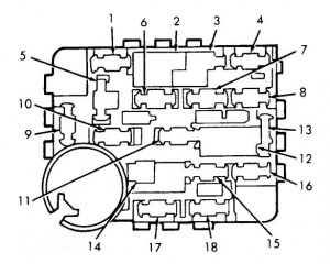
Lincoln Mark VIII (1993 – 1995) – fuse box diagram
Year of production: 1993, 1994, 1995
Interior fuse box panel
Fuse panel is located on the lower left side of the instrument panel, near the driver side door.

| Fuse | Ampere rating [A] | Functions |
| 1 | 30 | Blower Motor |
| 2 | 8.25 (Circuit Breaker) | Wiper/Washer (1993) |
| 3 | 30 | Wiper/Washer (1994) |
| 4 | 25 | Parking Lights |
| 5 | 10 | Rear Defrost, EATC, Brake Shift Interlock, Traction Control Switch |
| 6 | 15 | Courtesy Lights, Power Mirrors, Dome Switch, Remote Keyless Entry (1993), , Electronic Door Lock Control (1994), Memory Seats |
| 7 | 10 | Power Antenna, Anti-Theft Relay, Memory Seats |
| 8 | 20 | Cigarette Lighter |
| 9 | 10 | Transmission Control Switch, Autolight Sensor, Electrochromic Mirrors |
| 10 | 15 | Suspension/Steering Module, Electronic Flasher, Steering Wheel Position Sensor, Daytime Running Lights, Back-Up Lights, Air Bag (1993), Air Bag Diagnostic Monitor (1994) |
| 11 | 10 | Stoplights, Hazard Lights, Brake Pressure Switch |
| 12 | 20 (Circuit Breaker) | Power Seats, Fuel Door Release, Deck Lid Release, Shock Damping Control |
| 13 | 10 | Heated Mirrors, Compass |
| 14 | 20 (Circuit Breaker) | Moon Roof, Power Windows, One-Touch Down Module |
| 15 | 10 | Warning Light Bank, Instrument Cluster, Chime Module, Charge Light |
| 16 | 10 | Air Bag, Power Antenna, EATC, Warning Light Bank, CD Changer, Radio, Message Center |
| 17 | 15 | Anti-Theft System, Cellular Phone, Chime, Compass, Memory Seats, Message Center, Power Antenna, Radio, Remote Keyless Entry (1993), Electronic Door Lock Control (1994) |
| 18 | 10 | Chime, Front Parking Lights, Front Side Marker Lights, Instrument Panel Light Dimmer, Rear Parking Lights, Power Mirror Dimmer Control |
Underhood Fuse Panel
The high-current fuse panel is located in the engine compartment on the left hand fender apron.
| Fuse | Ampere rating [A] | Functions |
| 1 | 25 | Daytime Running Lights (Canada), Horn |
| 2 | — | Blank |
| 3 | 20 | Alternator |
| 4 | 15 | Air Suspension Control Module |
| 5 | 10 | Speed Control |
| 6 | — | Blank |
| 7 | — | Blank |
| 8 | 20 | PCM/CCRM (1993), PCM/VCRM (1994) |
| 9 | 30 | Anti-Lock Brake System |
| 10 | 50 | Ignition Switch Feeds: Ignition Switch: B2, B3, B5; Instrument Panel Fuses: 1, 10, 15, 17; Maxi Fuse: 22; PDF: 5; Instrument Panel C/B: 2, 14 |
| 11 | — | Blank |
| 12 | ABS Diode | Anti-Lock Brake System |
| 13 | 40 | Anti-Lock Brake Pump Motor |
| 14 | 40 | Headlamps |
| 15 | 40 | Rear Defrost |
| 16 | 40 | Engine Cooling Fan Control |
| 17 | 50 | Fuse Panel Feed: Instrument Panel Fuses: 4, 8, 16; Instrument Panel C/B: 12 |
| 18 | 40 | Ignition Switch Feeds: Ignition Switch: B1, B4, Instrument Panel Fuses: 2, 5, 9, 14, 17 |
| 19 | 40 | Fuse Panel Feed: Instrument Panel Fuses: 6, 11 |
| 20 | 50 | Air Suspension Compressor |
| 21 | 20 | Premium Sound, Cellular Phone |
| 22 | 20 | EDIS/CCRM (1993) Electronic Ignition/VCRM (1994) |
| 23 | Relay | Fuel Pump |
| 24 | Relay | Anti-Lock Brake Control Module |
| 25 | Relay | Horn |
| 26 | Relay | High/Low Autolights |
| 27 | Relay | Parking Lights, Autolights |
WARNING: Terminal and harness assignments for individual connectors will vary depending on vehicle equipment level, model, and market.