Lincoln Navigator (UN173; 1998) – fuse and relay box diagram
Year of production: 1998
This article covers the first-generation Lincoln Navigator, manufactured between 1998 and 2002. It includes fuse box diagrams for the 1998 models, provides details on the locations of the fuse panels within the vehicle, and explains the function and layout of each fuse and relay.
Engine compartment fuse panel
Fuse box location
The power distribution box is located in the engine compartment (on the driver’s side).
Fuse box diagram

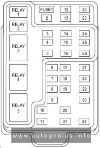
Assignment of the fuses and relays in the engine compartment (1998)
| No. |
A |
Circuit Protected |
| 1 | 15A | Flasher Relay |
| 2 | 5A | Instrument Cluster, Overhead Trip Computer (OTC) Module, Redundant Steering Control Module, Electronic Automatic Temperature Control (EATC) Module, Clock |
| 3 | 25A | Cigar Lighter |
| 4 | 5A | Park Lamp Relay, Headlamp Relay, Autolamp Module, Remote Anti-theft Personality (RAP) Module, Power Mirror Switch, Memory Seat and Mirror Module, Driver Power Seat Control Switch, Memory Seat Switch |
| 5 | 15A | Digital Transmission Range (DTR) Sensor, Daytime Running Lamps (DRL) Module, Speed Control Servo/Amplifier Assembly, EATC Clutch Relay |
| 6 | 5A | Shift Lock Actuator, Generic Electronic Module (GEM), 4 Wheel Air Suspension 4WAS Module, Compass Sensor, Steering Wheel Rotation Sensor, Heated Grid Relay, Overhead Trip Computer (OTC) Module |
| 7 | 5A | Auxiliary A/C Relay, Console Blower Motor |
| 8 | 5A | Radio, Main Light Switch, Remote Anti-theft Personality (RAP) Module, Generic Electronic Module (GEM), Ignition Switch, Clock |
| 9 | – | Not used |
| 10 | – | Not used |
| 11 | 30A | Washer Pump Relay, Wiper Run/Park Relay |
| 12 | 5A | Data Link Connector (DLC) |
| 13 | 15A | Brake On/Off (BOO) Switch, Brake Pressure Switch |
| 14 | 15A | Battery Saver Relay, Interior Lamp Relay |
| 15 | 5A | Generic Electronic Module (GEM), SecuriLock |
| 16 | 20A | Instrument Cluster (W/O DRL), Daytime Running Lamps (DRL) Module, Hi-Beam Headlamps (Power supplied through Multi-Function Switch) |
| 17 | 10A | Heated Backlite Switch, Left Power/Heated Signal Mirror, Right Power/Heated Signal Mirror |
| 18 | 5A | Main Light Switch, Generic Electronic Module (GEM), Instrument Illumination, (Power supplied through Main Light Switch), Park Lamp Relay, Trailer Electronic Brake Control, Trailer Tow Running Lamp Relay, Left Side Marker Lamps, Right Side Marker Lamps, Left Front Park/Turn Lamp, Right Front Park/Turn Lamp, Left Stop/Park/Tum Lamp, Right Stop/Park/Tum Lamp, Left License Lamp, Right License Lamp |
| 19 | 10A | Instrument Cluster, Air Bag Diagnostic Monitor |
| 20 | 5A | 4 Wheel Air Suspension 4WAS Generic Electronic Module (GEM), Memory Seat and Mirror Module |
| 21 | 15A | Digital Transmission Range (DTR) Sensor, Junction Box Fuse/Relay Panel (Fuse 20) |
| 22 | 10A | Air Bag Diagnostic Monitor, Ignition Swatch |
| 23 | 10A | Trailer Tow Battery Charge Relay, 4X4 Center Axle Disconnect Solenoid, 4X2 Center Axle Disconnect Solenoid, Electronic Day/Night Mirror, Rear Integrated Control Panel, Auxiliary A/C Mode Actuator, Auxiliary A/C Control Module, Auxiliary A/C Blend Actuator Flasher Relay |
| 24 | 10A | Electronic Automatic Temperature Control (EATC) Module, Console Blower Relay, Auxiliary A/C Relay |
| 25 | 5A | 4 Wheel Anti-Lock Brake System (4WABS) Module 4WABS Relay |
| 26 | 10A | Daytime Running Lamps (DRL) Module, Right Headlamp (Powder supplied through Multi-Function Swatch) |
| 27 | 5A | Main Light Swatch, Fog Lamp Relay |
| 28 | 10A | Left Headlamp |
| 29 | 5A | Autolamp Module, Instrument Cluster, Transmission Control Swatch (TCS) |
| 30 | 30A | Radio Noise Capacitor, PCM Power Diode, Coil on Plugs, PCM Powder Relay, SecuriLock |
| 31 | – | Not Used |
| 31 | 10 | Rear Integrated Control Panel (Audio), CD Player, Cell Phone |
Engine Compartment Fuse Box
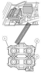
Power fuse box

Assignment of the fuses and relays in the power fuse box (1998)
| Location | Amperage | Description |
| 1 | 175 | Power Network Box Megafuse |
| 2 | 175 | Alternator Megafuse |
| 3 | 20 | Alternator Field Minifuse |
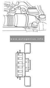
Additional fuse panel

Assignment of the fuses and relays in the additional fuse panel (1998)
| Slot number | Ampere rating [A] | Circuit protected |
| 1 | 5 | Powertrain Control Module (PCM) |
| 2 | 20 | Trailer Tow Stop/Turn Lamps |
| 3 | 10 | Audio Rear Integrated Control Panel (RICP), Compact Disc Changer, Radio |
| 4 | 10 | Running Board Lamps |
| 5 | 20 | Amplifier, Subwoofer Amplifier |
| 6 | — | Not used |
Passenger compartment box
Fuse box location
The fuse panel is located below and to the left of the steering wheel behind the cover.
Fuse box diagram

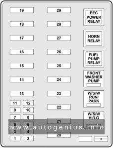
Assignment of the fuses and relays in the passenger compartment (1998)
| № | Amp Rating | Description |
|---|---|---|
| 1 | 20A | Trailer Tow Running Lamp Relay, Trailer Tow Backup Lamp Relay |
| 2 | 10A | Air Bag Diagnostic monitor |
| 3 | 30A | All Unlock Relay, All Lock Relay, Driver’s Unlock Relay |
| 4 | 15A | Air Suspension Sendee Switch |
| 5 | 20A | Horn Relay |
| 6 | 30A | Radio, Premium Sound Amplifier, CD Changer, Rear Integrated Control Panel, Sub-Woofer power |
| 7 | 15A | Main Light Switch, Park Lamp Relay |
| 8 | 30A | Main Light Switch, Headlamp Relay, Multi-Function Switch |
| 9 | 15A | Daytime running lamps (DRL) Module, Fog Lamp Relay |
| 10 | 25A | I/P Auxiliary Power Socket |
| 11 | 25A | Console Auxiliary Power Socket |
| 12 | 10A | Rear Wiper Up Motor Relay, Rear Wiper Down Motor Relay |
| 13 | 30A | Auxiliary A/C Relay |
| 14 | 60A | 4 Wheel Anti-Lock Brake System (4WABS) Module |
| 15 | 50A | Air Suspension Solid State Compressor Relay |
| 16 | 40A | Trailer tow battery Charge Relay, Mini Fuse Block (fuse 2), Trailer Tow Right Turn Relay, Trailer tow Left Turn Relay |
| 17 | 30A | Transfer Case Shift Relay, Torque on Demand Relay |
| 18 | 30A | Memory Seat Module |
| 19 | 20A | Fuel Pump Relay |
| 20 | 50A | Ignition Switch |
| 21 | 50A | Ignition Switch |
| 22 | 50A | Junction Box Fuse/Relay Panel Battery Feed |
| 23 | 40A | I/P Blower Relay |
| 24 | 30A | PCM Power Relay, Mini Fuse Block (fuse 1), Powertrain Control Module |
| 25 | 30A (CB) | Junction Box Fuse/Relay Panel, ACC Delay Relay |
| 26 | 30A | Passenger Power Seat Control Switch |
| 27 | 40A | Junction Box Fuse/Relay Panel, Heated Grid Relay |
| 28 | 30A | Trailer Electronic Brake Control |
| 29 | 30A | RPO Relay Block, Vent Window/Moonroof Relay |
WARNING: Terminal and harness assignments for individual connectors will vary depending on vehicle equipment level, model, and market.
