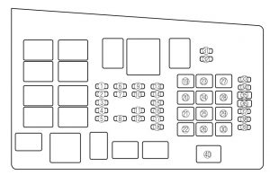
Mazda 6 (2004) – fuse box diagram
Year of production: 2004
Fuse block (Engine compartment)

engine compartment
| Position | Description | Fuse rating [A] | Protected component |
| 1 | SPARE | 20 | — |
| 2 | SPARE | 15 | — |
| 3 | SPARE | 10 | — |
| 4 | — | — | — |
| 5 | — | — | — |
| 6 | INJ | 15 | Injector |
| 7 | ENG BAR | 10*1 | Air flow sensor, EGR control valve |
| 15*2 | |||
| 8 | ENG BAR2*1 | 15 | O2 sensor |
| ENG BB*2 | 5 | Cooling fan | |
| 9 | HEAD LR | 10 | Headlight-low beam (Right) |
| 10 | HEAD LL | 10 | Headlight-low beam (Left) |
| 11 | HEAD HL | 10 | Headlight-high beam (Left) |
| 12 | HEAD HR | 10 | Headlight-high beam (Right) |
| 13 | ETC | 7,5 | Accelerator position sensor |
| 14 | HAZARD | 10 | Turn signal lights |
| 15 | STOP | 15 | Brake/Taillights |
| 16 | TCM*1 | 10 | TCM |
| IG1*2 | 15 | O2 sensor | |
| 17 | ENG + B | 7,5 | PCM, TCM |
| 18 | FUEL PUMP | 15 | Fuel pump |
| 19 | IG KEY | 40 | Windshield wiper and washer, Engine control unit, Lighter |
| 20 | P.WIND | 30 | Power window |
| 21 | — | — | — |
| 22 | — | — | — |
| 23 | IG KEY2 | 30 | Reverse lights, Heater control unit |
| 24 | BLOWER | 40 | Blower motor |
| 25 | BTN | 40 | Overhead light, Power door lock |
| 26 | — | — | — |
| 27 | DEFOG | 40 | Rear window defroster |
| 28 | ABS | 60 | ABS |
| 29 | AD FAN*1 | 30 | Cooling fan |
| FAN2*2 | |||
| 30 | FAN*1 | 30 | Cooling fan |
| FAN1*2 | |||
| 31 | TAIL | 10 | Dashboard illumination |
| 33 | MAG | 10 | Magnet clutch |
| 34 | AUDIO | 15 | Audio system |
| 35 | P.SEAT | 30 | Power seat |
| 36 | OPENER | 7,5 | Fuel lid opener |
| 37 | — | — | — |
| 38 | — | — | — |
| 39 | FOG | 15 | Fog lights |
| 40 | MAIN | 100A*1 | For protection of all circuits |
| METER3 | 120A*2 | ||
| *1 2.5-liter engine
*2 3.7-liter engine |
|||
Fuse block (Left side)
vehicle’s left side
| Position | Description | Fuse rating [A] | Protected component |
| 1 | ENGINE IG | 15 | Engine control system |
| 2 | METER IG | 15 | Instrument cluster |
| 3 | SEAT | 15 | Seat warmer, Rear window defroster |
| 4 | M.DEF | 7,5 | Mirror defroster |
| 5 | WIPER | 20 | Windshield wiper and washer |
| 6 | SAS | 15 | ABS unit, SAS unit |
| 7 | BACK | 5 | Reverse lights |
| 8 | A/C | 15 | Heater |
| 9 | METER ACC | 5 | Instrument cluster |
| 10 | CIGAR | 15 | Lighter |
| 11 | ROOM | 15 | Overhead light |
| 12 | — | — | — |
| 13 | MIRROR | 5 | Power control mirror, Audio system |
| 14 | R.CIGAR | 15 | Accessory socket |
| 15 | — | — | — |
| 16 | D.LOCK | 30 | Power door lock |
| 17 | — | — | — |
WARNING: Terminal and harness assignments for individual connectors will vary depending on vehicle equipment level, model, and market.