Mazda 626 (1991 – 1997) – fuse box diagram
Year of production: 1991 ,1992, 1993, 1994, 1995, 1996, 1997
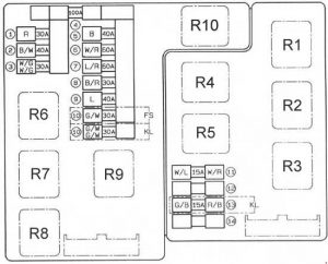
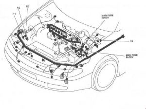
Fuse box in the engine compartment

| Position | Description | Fuse rating [A] | Protected component |
| 1 | HEAD | 30 | Headlight Daytime Running Lights (DRL) |
| 2 | DEFOG | 40 | Rear Window Defroster |
| 3 | EGI INJ | 30 | Charging System Engine Control System EC-AT Control System (FS) ATX Ignition System (FS) ATX Fuel Control System (FS) Fuel Control System (KL) Ignition System (KL) |
| 4 | MAIN | 40 | Ignition Switch (Fuse No.: 5, 6, 8, 10, 11, 13 (passenger compartment fuse box)) |
| 6 | BTN | 60 | Fuse No.: 11 Fuse No.: 1, 2, 3, 7, 9 (passenger compartment fuse box) |
| 7 | ABS | 60 | Antilock Brake System |
| 8 | COOLING FAN | 30 | Coolant Fan System |
| 9 | HEATER | 40 | Heater and Air Conditioner |
| 10 | AIR-COND | 30 | Condenser Fan System |
| 11 | TAIL | 15 | Tail Lights Parking Lights Illumination Lights License Plate Light Front Side Marker Lights Rear Side Marker Lights Glove Box Light |
| 12 | * | ||
| 13 | FOG | 15 | Front Fog Lights |
| 14 | * | ||
| Relay | |||
| R1 | Starter Interrupt Relay Headlight High Relay |
||
| R2 | Main Relay | ||
| R3 | Fuel Pump Relay | ||
| R4 | Horn Relay | ||
| R5 | Daytime Running Lights (DRL) Relay | ||
| R6 | Cooling Fan Relay No.3 | ||
| R7 | Cooling Fan Relay No.2 | ||
| R8 | Cooling Fan Relay No.1 | ||
| R9 | A/C Relay | ||
| R10 | A/C Relay | ||
Passenger compartment fuse box

| Position | Description | Fuse rating [A] | Protected component |
| 1 | STOP | 20 | Brake Lights High Mounted Brake Light Horns Cruise Control System Shift-Lock System |
| 2 | ROOM | 15 | Courtesy Lights Vanity Mirror Lights Trunk Compartment Light Audio System Power Door Locks Power Door Locks (with keyless entry system) Power Antenna Theft-Deterrent System Central Processing System Instrument Cluster EC-AT Control System Spot Lights Interior Light Ignition Key Illumination Engine Control System Ignition System |
| 3 | DOOR LOCK | 30 | Power Door Locks Power Door Locks (with keyless entry system) |
| 4 | RADIO | 15 | Audio System Cigarette Lighter Power Antenna Power Outside Mirrors |
| 5 | SUNROOF | 15 | Sliding Sunroof |
| 6 | TURN | 15 | Turn and Hazard Warning Lights Air Bag System |
| 7 | POWER SEAT | 30 | Power Seat |
| 8 | METER | 15 | Back-Up Lights Data Link Connector Instrument Cluster EC-AT Control System Theft-Deterrent System Central Processing System Power Antenna Cruise Control System Shift-Lock System Engine Control System (FS) ATX Ignition System (FS) |
| 9 | HAZARD | 15 | Turn and Hazard Warning Lights |
| 10 | ENGINE | 15 | Engine Control System MTX Fuel Control System (FS) Ignition System Starting System EC-AT Control System (FS) Coolant Fan System Heater and Air Conditioner Antilock Brake System Air Bag System Rear Window Defroster |
| 11 | POWER WINDOW | 30 | Power Windows |
| 12 | HEAD CLEANER | 20 | Headlight Cleaner |
| 13 | WIPER | 20 | Windshield Wiper and Washer Heater and Air Conditioner Condenser Fan System Daytime Running Lights (DRL) Engine Control System (FS) EC-AT Control System (FS) Ignition System (FS) |
| 14 | REAR WIPER | 20 | Rear Wiper & Washer |
| 15 | SPARE | 15 | Spare |
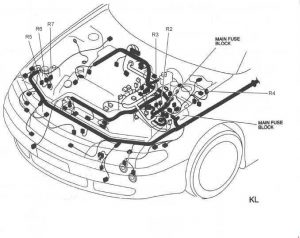
Relay
FS

KL

| Number | Relay |
| R1 | Blower Relay |
| R2 | Headlight Relay |
| R3 | Rear Window Defroster Relay |
| R4 | TNS Relay |
| R5 | Condenser Fan High Relay No.2 |
| R6 | Condenser Fan Low Relay |
| R7 | Condenser Fan High Relay No.1 |
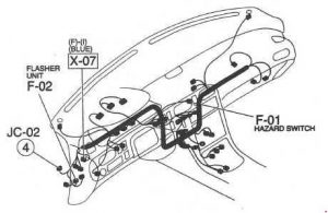
Flasher Unit
626

WARNING: Terminal and harness assignments for individual connectors will vary depending on vehicle equipment level, model, and market.
